DISASSEMBLE
- Separate upper body from lower body taking care to avoid damage to float. Remove and save all parts from upper and lower bodies.
- Clean both castings thoroughly in carburetor cleaner solvent.
- Blow out all channels and passages with compressed air. Be sure castings are clean.
REASSEMBLE
- Carefully inspect all parts to make sure that they have been thoroughly cleaned and that all jet passages are clear.
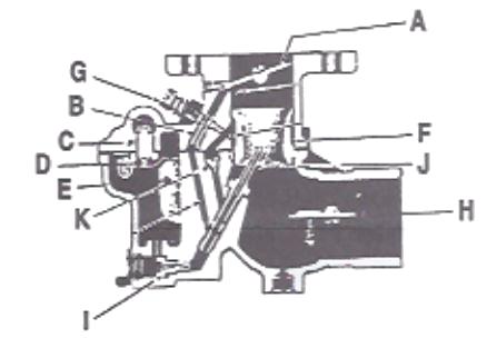
- Install throttle shaft, retainer and packing in position, then insert throttle plate (A). Back off idle screw on throttle shaft so throttle plate will close tight. Insert screws and tighten securely. If throttle shaft binds turn to closed position and lightly tap shaft directly over center of throttle plate.
- Install throttle throw lever in same position as removed. (some models throttle throw lever and throttle stop lever are in one assembly).
- Install idling jet (B) using small screw driver.
- Install fuel valve seat (C) and new gasket.
- Place new body to bowl gasket in position.
- Place fuel valve needle (D) in position, then insert float (E) and float axle. Float must move freely.

8. To obtain correct fuel level check position of float to measure 1 5/32″ plus or minus 3/64″ from casting to farthest point of float. Bend float arm next to float to obtain this measurement. DO NOT BEND FLOAT HINGE.
9. Place the venturi (F) in position in the throttle body. Locating boss on venturi fits in groove on throttle body on 161 series.
10. Install idling adjust screws (G) and spring.
11. Place choke shaft in position in bowl casting and install air shutter plate (H). Turn choke shaft to closed position and insert screws and lock washers. Be sure choke plate is properly centered before tightening screws securely.
12. Install choke shaft hole plug and install retainer screw.
13. Hold choke bracket in position and install retainer screw.
14. Install choke lever assembly. Check operation of choke to make sure it opens and closes freely.
15. Install main jet (I) and new gasket.
16. Install main jet adjustment assembly and gasket over main jet. (Some models do no have main adjustment assembly).
17. Install main discharge nozzle (J) and gasket.
18. Replace well vent (K).
19. Place the bowl assembly in position on throttle body being careful to avoid damage to float.
20. Install assembly screws and lock washers. Be sure to tighten screws evenly and securely.
PRIMAY ADJUSTMENTS
- Set idle screw on throttle shaft one complete turn off stop pin.
- Set idle adjusting needle one full turn off seat.
- Set main adjusting needle one turn off seat.