
Fast Idle and Unloader
During the warm-up period, it is necessary to provide a fast idle speed to prevent engine stalling. This is accomplished by a fast idle cam connected to the choke shaft. The choke trip lever contacts the fast idle cam. The fast idle link attached to the throttle lever contacts the choke trip lever and prevents the throttle valve from returning to a normal warm engine idle position while the automatic choke is in operation.
If during the starting period the engine becomes flooded, the choke valve may be opened manually to clean out any excess fuel in the intake manifold. This may be accomplished by depressing the accelerator pedal to the floor mat and engaging the starter. The unloader projection on the fast idle link will contact the unloader lug on the choke trip lever and in turn partially open the choke valve.
EGR Control
All vehicles since 1973 have used an EGR, or “Exhaust Gas Recirculation,” system to lower emissions of nitrogen oxides.
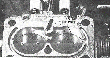
The EGR valve is controlled either by a port in the throttle body above the closed throttle valve or by venturi vacuum.
The ported EGR control takes advantage of the throttle valve position to open the EGR valve. At idle, the port is on the atmospheric side of the throttle valve keeping the EGR valve closed. As the throttle valves are opened, the port is exposed to the manifold vacuum which opens the EGR valve.
The ported EGR uses a notched throttle valve to reduce sensitivity for smoother EGR operation.
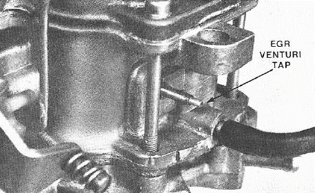
Some models use the venturi vacuum control system whereby a vacuum tap at the throat of the carburetor venturi is used to provide a control signal.
Wide Open Throttle Dump Valve
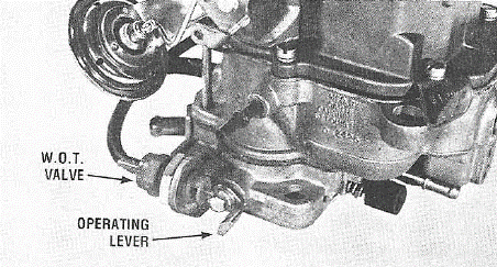
Some applications use a W.O.T., or “Wide Open Throttle,” dump valve for the EGR system. The dump valve will “kill” the venturi signal to the atmosphere. The dump valve is in series with the EGR venturi port in the carburetor and the amplifier. At wide-open throttle, the arm on the throttle shaft opens the dump valve cutting off the EGR and giving full horsepower.
Throttle Positioner Solenoid
In some applications, the BBD carburetor uses a throttle positioner solenoid as part of a catalyst protection system. The system’s function is to prevent unburned hydrocarbons from entering the atmosphere through the vehicle’s exhaust system when the engine is decelerated from a high RPM.
The solenoid works in conjunction with an electronic speed switch and positions the throttle valves during rapid deceleration to prevent over-rich mixtures contaminating the catalytic converter.
The electronic speed switch senses the pulses from the electronic ignition system. When the engine is operating above approximately 2,000 R.P.M., the electronic speed switch energizes the throttle positioner solenoid. On deceleration, the throttle positioner solenoid holds the throttle valves to approximately 1,800 R.P.M. When engine speed drops below 2,000 R.P.M., the throttle positioner solenoid is de-energized allowing the throttle valves to close. Thus, the converter is protected from overheating.
Some California units use a vacuum throttle positioner which consists of an electronic speed switch, an electrically controlled vacuum solenoid valve, and a vacuum activated positioner.
Its function and operation are the same as the solenoid type positioner above.
Dashpot
Some applications use a slow closing throttle device commonly called a dashpot. They are used to delay or slow the throttle closing the last few degrees to prevent engine stalling at the lower speeds and also to eliminate a sudden peak of hydrocarbon emissions on sudden deceleration. At idle, the manifold pressure is very low and results in good vaporization of the air-fuel mixture in the intake manifold.
When the throttle valve is opened, manifold pressure increases. This increase in pressure in creases the boiling point of the liquid and prevents 100% vaporization of the air-fuel mixture. During these periods of high manifold pressures, there are some wet particles of fuel clinging to the inside of the intake manifold which is known as “wet manifold.”
During sudden deceleration, the manifold pressure goes back to a low-pressure state, the wet particles clinging to the inside of the intake manifold go back to a vapor state and are taken into the engine as a rich mixture. This is known as “manifold flash” and can cause the engine to die out, especially at low speeds. The dashpot slows the closing of the throttle the last few degrees to give the engine time to clear itself of manifold flash.
Purge Port
Starting in 1971 all outside carburetor vents had to be routed to a canister to prevent evaporative emissions to the atmosphere. A purge port has been added to the carburetor to purge the canister of these fuel vapors. The purge port is located above the throttle valve. As the throttle valves open, the purge port is exposed to low pressure which gives a predetermined airflow to scavenge these vapors from the canister.
Port relation is the position of the throttle valve relative to the idle port. Anything that changes this relationship will seriously affect idle, acceleration, E.G.R., spark and purge timing. Proper idle adjustment for correct positioning of the throttle valves is most important.
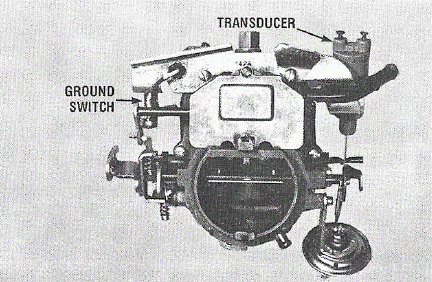
Transducer and Ground Switch
Carburetors used on the lean-burn engines use a throttle position transducer and a ground switch. The transducer is simply a device that changes mechanical motion to an electrical signal. It consists of a coil enclosed in plastic with a moveable iron core which is attached by linkage to the throttle lever. Its movement and position are always relative to throttle position and throttle movement. The transducer signals the E.S.A., or “Electronic Spark Advance,” computer the position and rate of change of the throttle. The E.S.A. then adjusts ignition timing to coincide with throttle position and rate of opening.
The function of the ground switch is to signal the E.S.A. computer when the throttle valves are closed. The E.S.A. retards timing at closed throttle position.
Some models incorporate a grounding switch to control the distributor solenoid. When the throttle valves are at idle position, the grounding switch grounds the distributor solenoid which retards ignition timing.
The O2 Feedback System Using Variable Air Bleeds
Carburetor Operation
The basic carburetor contains two fuel supply subsystems, the high-speed system, and the low-speed system. The high-speed system meters fuel with a tapered metering rod positioned in the jet by the throttle. Fuel is metered into the main nozzle well, where air from the feedback-controlled variable air bleed is introduced. Since this air is delivered above the fuel level, it reduces the vacuum signal on the fuel, consequently reducing the amount of fuel delivered from the nozzle.
The idle system is needed at low air flows through the venturi because there is an insufficient vacuum at the nozzle to draw fuel into the air stream. After leaving the main jet, fuel is supplied to the idle system by the low-speed jet. It is then mixed with air from the idle by-pass, then accelerated through the economizer and mixed with additional air from the idle bleed before being discharged from the idle ports below the throttle. Air from the variable air bleed is introduced between the economizer and idle bleed. This air reduces the vacuum signal on the low-speed jet and consequently the amount of fuel delivered to the idle system.
The variable air bleeds change the pressure difference which controls fuel flow thru the jets.
Two types of air metering control are used on the BBD O2 feedback system. The stepper motor with air metering pins is used on some applications, while others use a pulsed solenoid.
BBD With Stepper Motor
The variable air bleeds consist of tapered metering pins positioned in orifices by the stepper motor. This drive mechanism moves the pins in defined steps in response to signals from the oxygen sensor located in the exhaust and processed by the electronic control unit. The stepper motor moves the pins until the exhaust sensor indicates that the desired air-fuel ratio has been reached. Thus the pin movement adjusts the air-fuel ratio to compensate for changes detected in the exhaust gases.
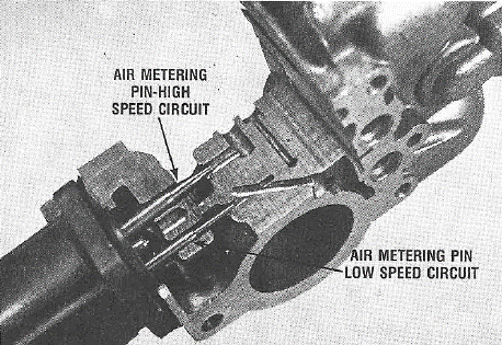
Stepper Motor & Air Metering Pins
The digital linear actuator or stepper motor moves the metering pins, .400 inches from full lean to full rich. Full movement requires 100 steps at .004 inches per step.
Fast speed is 100 steps per second, slow speed is 12 steps per second.
During the initial power-up of the stepper motor, the metering pins must be sent to an end stop to give the electronic control unit a stable reference. The metering pins must then be backed off to the desired position.
This initialization of the metering pins occurs in open-loop mode. When the ignition is turned on, and again when the starter is engaged, the metering pins move inward (rich position) 127 steps and outward (lean position) 35 steps. This locates the pins near the position to give the average air-fuel ratio for complete fuel combustion (stoichiometric ratio).
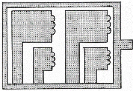
Coil Windings
The stepper motor incorporates a unipolar winding which has 2 coils wound on the same bobbin, per stator half, for a total of 4 coils.
A threaded shaft provides linear movement which is bidirectional. Movement and direction is controlled by motor phasing sequence.
Checking Stepper Motor
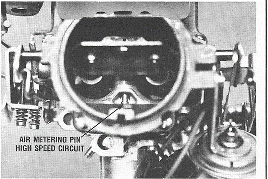
To check stepper operation, remove the air cleaner from the carburetor. The air metering pin for the high-speed circuit is visible looking into the air horn of the carburetor.
Turning the ignition switch on should cause the initialization of the air metering pins. If no movement is observed, check electrical connections and windings.

Checking Coils
Check each winding of the stepper motor by disconnecting the wiring harness from the stepper motor. With an ohmmeter, check each coil by connecting to the “C” terminal and to the ground terminal of each coil. There should be 78 ohms, plus or minus 25 ohms at room temperature.
Movement of the air metering pins can be accomplished by applying 12 volts to the “C” terminal and grounding the coils as per the phasing sequence.

Air Management Switch
On some applications with an O2 feedback system, a microswitch is incorporated which is operated by the throttle shaft. It is part of the air management system and makes contact at 25 degrees before wide-open throttle. When contact is made, it dumps the air pump air to the atmosphere.
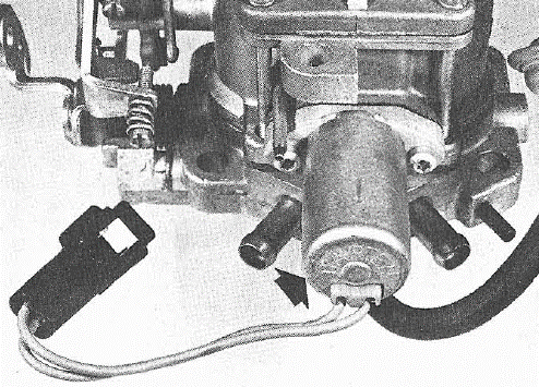
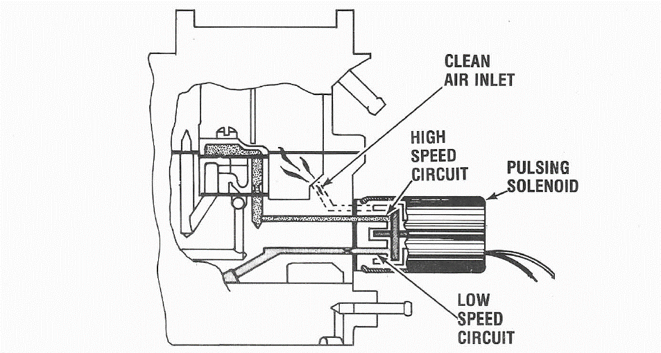
BBD With Pulse Solenoid
Some models use a pulsed solenoid to control the variable air bleeds. This eliminates the metering pins, as the pulse cycle controls the air-fuel ratio.
The solenoid has only two positions of operation, opened when energized to bleed air to both the high speed and low-speed circuits, or closed when deenergized, cutting off the air bleeds.

Pulse Width Modulation
During normal operation, the solenoid goes through one open and one closed period in each cycle. The pulse solenoid is 10 Hz. frequency (10 cycles per second) which adds up to 100 Mil per second per cycle.
Each cycle has a particular time period, ‘T’, from the beginning of one cycle to the next and is held constant during operation (always 10 cycles per second).
During any one cycle, the solenoid is open for some fractional period of time, “t”. The duration of “t” can be varied, thus varying the duty cycle and amount of air bleed to the carburetor circuits.
100% duty cycle means full air bleed for approximately 100 Mil per second per cycle. This duty cycle may be varied from zero percent to one hundred percent.
Pulse width modulation of the airflow is controlled by the solenoid duty cycle as signaled by the computer.
Specification: Resistance 22 plus or minus 1 ohm at room temperature
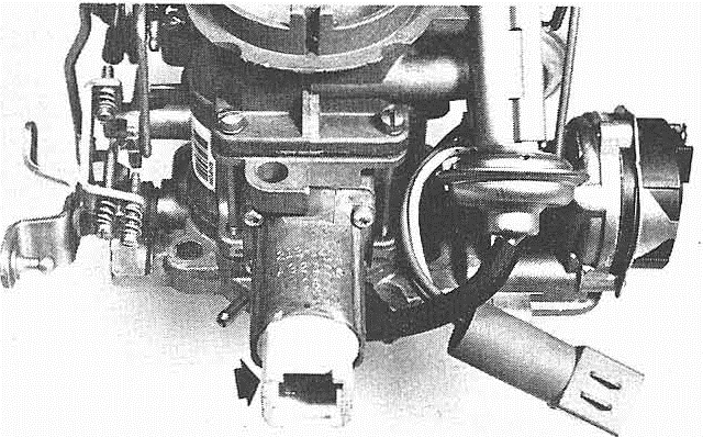
Checking Pulse Solenoid
Checking the pulse solenoid is very quick and easy. With the engine at operating temperature, merely place a hand on the solenoid. if not pulsing, shut off the engine and disconnect pulse solenoid wires.
Check for open or shorted coil winding by using an ohmmeter across the two blue wires. (The coil is not grounded to the case). Should be 22 ohms resistance at room temperature.
If winding is working properly, momentarily flash 12 volts to pulse solenoid to check armature movement.
A dwell meter can be used with the pulse solenoid to give an overall indication of the operation. The dwell reading would be indicative of the ratio of “on” to “off” time which is referred to as pulse width modulation. With the engine warmed up, place fast idle cam to obtain approximately 1200 R.P.M. and check to dwell reading. Closing the choke valve slightly to richen the air-fuel mixture should give an increase in dwell.
A command from the computer to “lean out” would give a dwell reading between 30 to 60 degrees dwell, a rich command would read between 0 to 30 degrees dwell. An ideal reading would be between 28 to 32 degrees.
The dwell meter should always be set on the 6-cylinder scale.