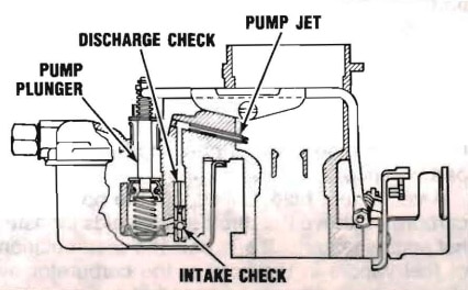
The accelerating pump circuit provides the measured amount of fuel necessary to assure smooth engine performance during acceleration at lower car speeds.
As the throttle is closed, the accelerating pump plunger is raised in the cylinder and fuel from the bowl flows into the pump cylinder through the intake ball check located at the lower end of the cylinder.
No air enters the cylinder due to the sealing action of the pump discharge needle being on its seat.
As the throttle is opened, the plunger moves downward in the cylinder, forcing fuel past the discharge needle and out through the pump jet into the air stream.
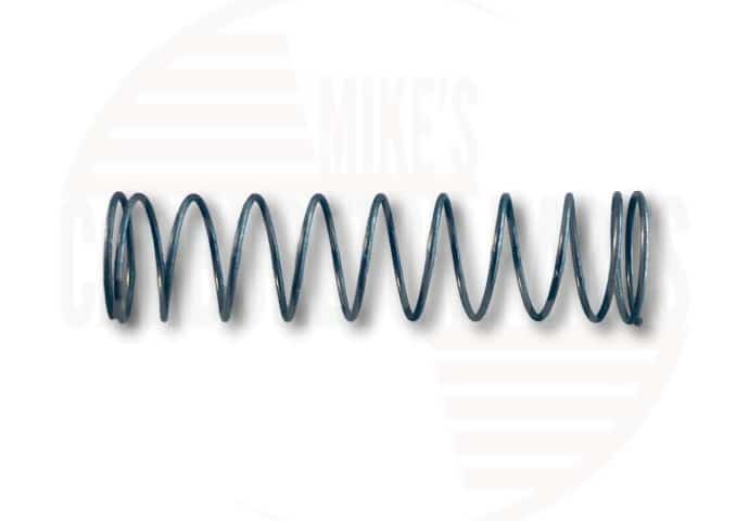
During the discharge stroke, the intake ball is on its seat to prevent fuel from flowing back into the bowl. The spring on the connector link, or the heavy drive spring above the plunger (some models) and the size of the pump jet provide a pump discharge of the desired duration. The light upper pump spring merely holds the bowl vapor vent washer on its seat and plays no part in pump action.
On some applications the pump intake check was removed from the lower end of the pump cylinder and placed adjacent to the cylinder. The intake check plug can be removed for service. In the same passage, directly above the intake check is the discharge needle. This cannot be removed for service.
Pump Jet Aim
An incorrectly aimed pump jet can cause a “flat spot on acceleration.” The pump discharge should strike the venturi strut 1/32 to 3/32 inch from outer edge of venturi and it should strike the upper edge so that almost all of the discharge diffuses over the top of the strut.
If correction is required, be sure that the tip of the jet is not damaged.
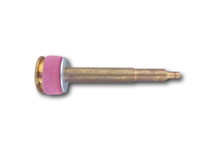
Accelerator Pump Styles
There are two pump styles used on the Carter RBS carburetor
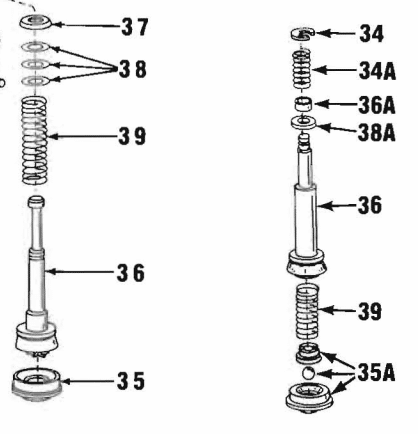
1970 and later models
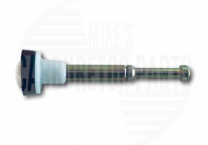
Early (pre 1970) models