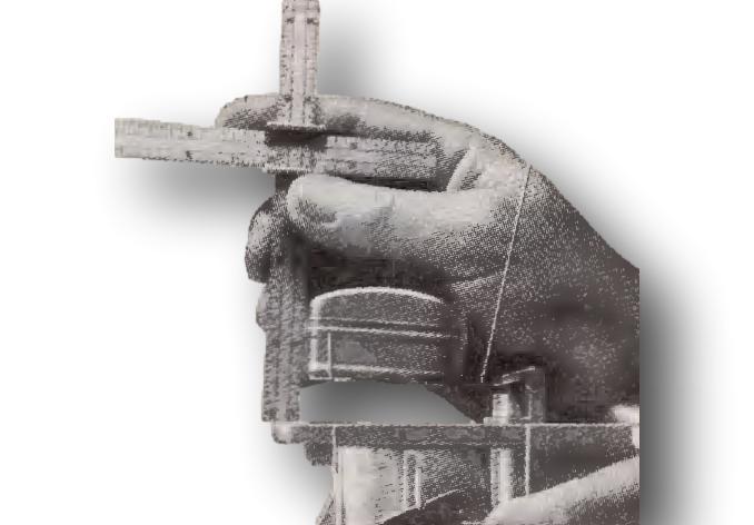
Float Level
invert the air horn assembly, and check the clearance from the top of the float to the bottom of the air horn with the float level gauge. Hold the air horn at eye level when gauging the float level. The float arm (lever) should be resting on the needle pin. Do not put pressure on the needle when adjusting the float as it will damage the Viton tip. Bend the float arm as necessary to adjust the float level (clearance). Do not bend the tab at the end of the float arm. It prevents the float from striking the bottom of the fuel bowl when empty. Use the float level specification from here or from the carburetor manual
Float Drop
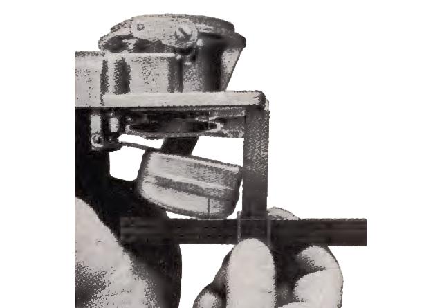
Hold air horn upright and measure maximum clearance from top of float to bottom of air horn with float drop gauge. Bend tab at end of float arm to obtain specified· setting listed under YF Adjustment Specifications.
Accelerator Pump Adjustment
With throttle valve seated in bore of carburetor, press down on upper end of diaphragm shaft until it reaches its bottom position. The metering rod arm should now contact the pump lifter link at the outer end nearest the springs. Adjust by bending the pump connector link at its lower angle. Some later YFA models have a screw at the top for adjustment.
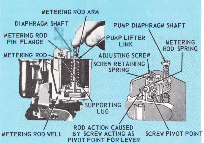
Metering Rod Adjustment
Back out the idle speed adjusting screw until the throttle plate is closed tight in the throttle bore. Press down on upper end of diaphragm shaft until diaphragm bottoms in vacuum chamber. Metering rod should contact bottom of metering rod well, and metering rod should contact lifter link at the outer end nearest the springs and at supporting lug. For models not equipped with metering rod adjusting screw, adjust by bending lip of metering rod arm to which metering rod is attached, up or down as required. For models equipped with a metering rod adjusting screw, turn the adjusting screw until metering rod just bottoms in the body casting, For final adjustment turn metering rod adjusting screw in (clockwise) one additional turn.
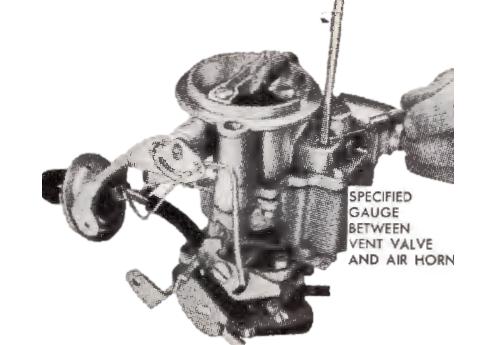
Idle Vent Adjustment
This adjustment should be made after completing pump and metering rod adjustments. Install bowl cover and air horn assembly with gasket. With throttle valve tightly closed in carburetor bore there should be the clearance listed in the YF Specifications Chart between idle vent valve and inside of bowl cover. Adjust idle vent screw as required.

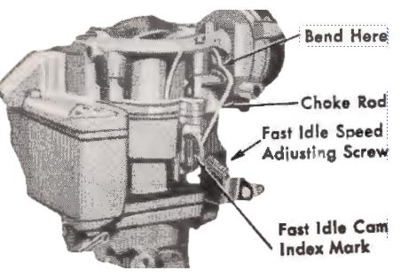
Fast Idle Cam Adjustment
Unit with build-in automatic choke
Remove choke coil housing, gasket and baffle plate. Crack throttle valve (barely open) and hold choke valve firmly in closed position, then close throttle valve. This will allow the fast idle cam to revolve to the fast idle position.
Clearance on 1969-70 Ford units is measured between the throttle valve and the throttle bore (side opposite idle port). Clearance on 1971-74 Ford and 1974 American Motors units is measured between lower edge of choke plate and the carburetor bore.
With choke valve held tightly closed, and slight tension on throttle lever, refer to YF Specifications when adjusting units with throttle valve to throttle bore clearance settings.
NOTE: Caution: The choke trip lever must not contact the fast idle cam during adjustment. All other units should have the fast idle adjusting screw aligned with the index mark at the back side of the cam. If cam has no index mark, position the fast idle screw on the kickdown step of the fast idle cam against the shoulder of the high step. Adjust linkage by bending the choke rod at elbow.
The 1970-73 American Motors units have engine fast idle RPM settings in place of specified carburetor to choke plate clearance. Refer to YF Specifications Chart. Adjustment is same as above.
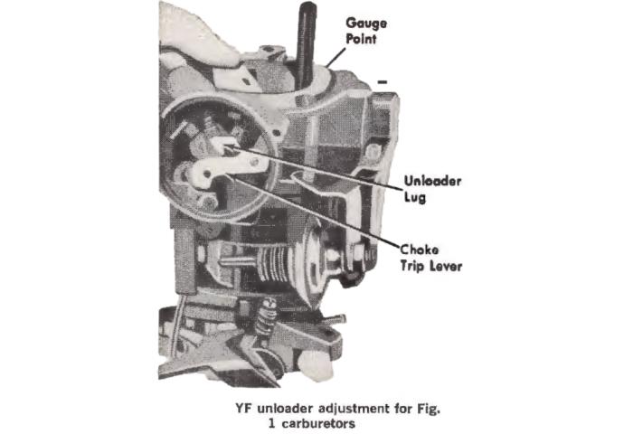
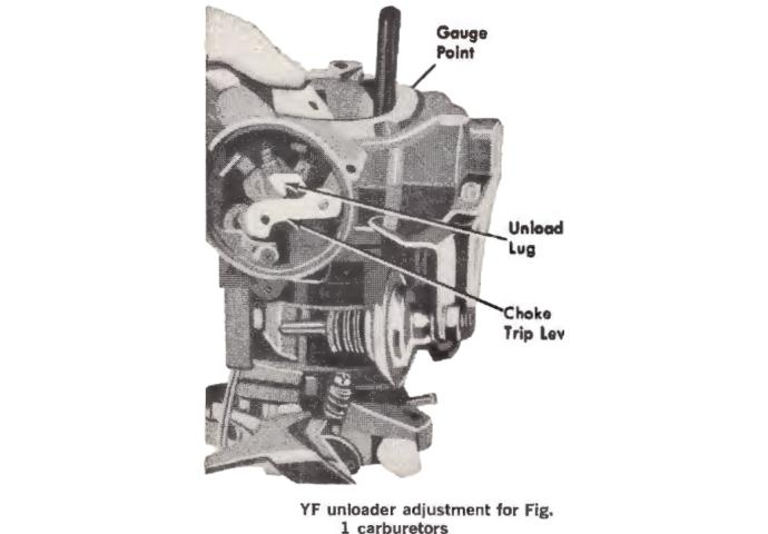
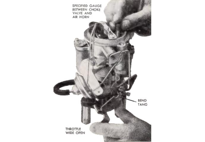
Choke Unloader Adjustment
With throttle valve held wide open and choke valve held toward closed position with a rubber band, there should be the clearance listed in the YF Specifications Chart between lower edge of choke valve and inner air horn wall.
On Fig. 1 carburetors, adjust by bending unloader lug on choke trip lever, On Fig. 2 carburetors adjust by bending unloader tang on throttle lever, Fig. 9.
NOTE: On 1974 American Motors models, the choke unloader adjustment has been eliminated. It is only necessary to check for full throttle opening when throttle is operated from inside the vehicle.
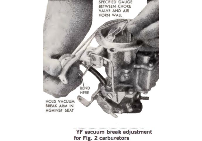
Vacuum Break Adjustment
With vacuum break arm held against its top, and choke valve held toward closed position with a rubber band, bend vacuum break link to obtain the clearance listed in the YF Specifications Chart between lower edge of choke valve and air horn wall.
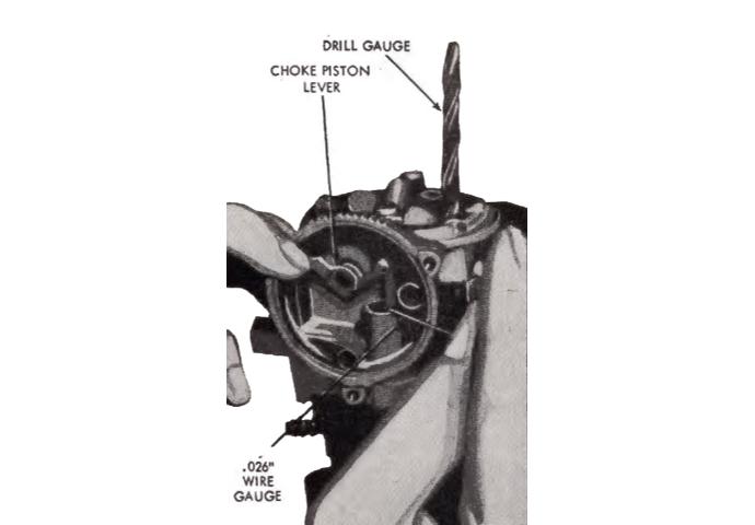
Choke Plate Pulldown Adjustment
For Fig. l Units
Bend a 0.026 in. diameter wire gauge at a 90 degree angle approximately ¼-inch from one end. Insert the bent end of the
gauge between the choke p,iston slot and the right hand slot in choke housing. Rotate the choke piston lever counterclockwise until gauge is snug in the piston slot. Exert a light pressure on choke piston lever to hold the gauge in place, then use a drill with a diameter equal to the specified pulldown clearance between the lower edge of choke plate and carburetor bore to check clearance, Fig. 11.
To adjust the choke plate pulldown clearance, bend the choke piston lever as required to obtain specified setting.
NOTE: When bending the lever, be careful not to distort the piston link. Install the choke thermostatic spring housing and gasket. Set the housing to specifications.
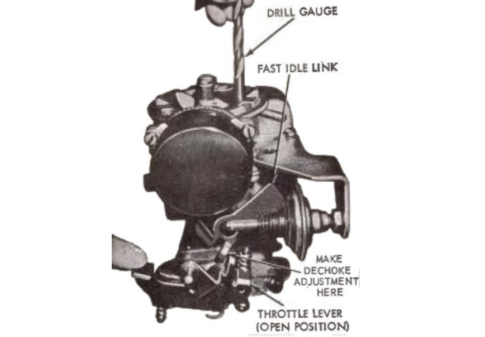
Dechoke Adjustment
For Fig. la Units
Hold the throttle plate fully open and close the choke plate as far as possible without forcing it. Use a drill of specified diameter to check the clearance between choke plate and air horn, Fig. 12. If clearance is not with in specification, adjust by bending arm on choke trip lever of the throttle lever. Bending the arm downward will decrease the clearance, bending it upward will increase the clearance.
If the choke plate clearance and fast idle cam linkage adjustment was performed with the carburetor on the engine, adjust the engine ,idle speed and fuel mixture. Adjust dash pot (if so equipped).
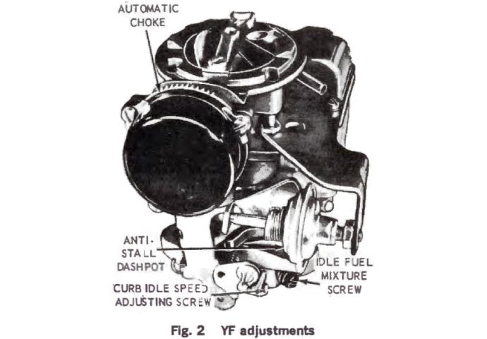
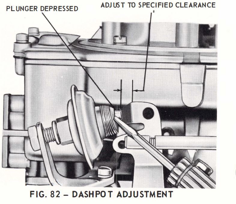
Dashpot Adjustment
With the engine idle speed and mixture properly adjusted, the engine at normal operating temperature, loosen the antistall dashpot lock nut, Hold the throttle in the curb idle position and depress the dashpot plunger. Measure the clearance between the throttle lever and plunger tip. Turn the anti-stall dashpot to provide 7/64″ ± 1/64″ clearance between the tip of the plunger and the throttle lever. Tighten the locknut to secure the adjustment.
Automatic Choke Adjustment
For Figs. 1, la, 2a and 2b Units
Loosen choke cover retaining screws and turn choke cover so that line or Index mark on cover lines up with the specified mark listed in YF Specifications Chart on choke housing.
When there are no index marks – With throttle open, twist the thermostat until the choke closes then give it another 1/8 turn.
Choke Diaphragm Linkage Adjustment
For Fig. 2 Units
With vacuum diaphragm bottomed, close choke valve as far as possible with· out forcing. Adjust choke diaphragm connector rod to give the clearance listed in the YF Specifications Chart between lower edge of choke valve and inner wall of air horn. Remove connector rod to prevent damage to diaphragm.