Float Level Adjustment
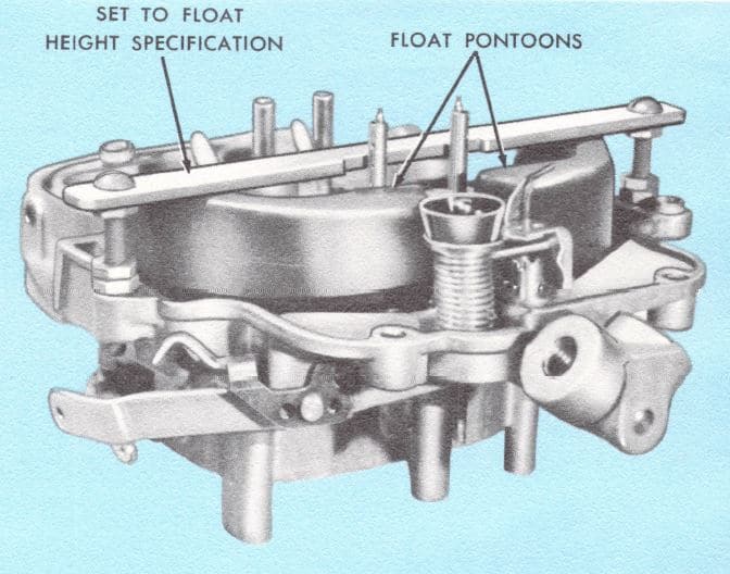
There are 2 float adjustments, one for the main or primary valve and one for the auxiliary valve. The float setting, which controls the fuel level in the bowl, is critical because the fuel level affects calibration. In most cases the auxiliary won’t need adjusting since most will be plugged off.

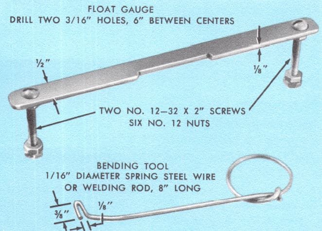
Below is an illustration of tools you can make for adjusting the float.
To adjust the float setting:
- Adjust both nuts on the gauge to the float height specification provided in either a shop manual, or the instruction sheet from your carburetor kit.
- Insert the ends of the gauge screws in the outboard holes of the air horn.
- Align the pontoons if required by bending the metal only. Do not bend the pontoons or it may cause a leak.
- Bend the primary tab in the float lever as required so that both pontoons just touch the gauge.
- To raise the float, insert the open end of the bending tool between the needle and float hinge. Raise the float level off the needle and bend the tab downward. Putting pressure on the needle will cause it to leak.
- To lower the float, insert the open end of the tool between the needle and float tab. Support the lever and bend the tab upward.

Fast Idle Speed

When equipped with spark delay device, set fast idle with ambient temperature above 55 deg with a vacuum line connected directly from carburetor spark port to advance side of distributor and vacuum line to EGR valve disconnected and plugged.
For more 4300 adjustments buy our helpful manual.
Idle Speed and Mixture Adjustment
A preliminary idle adjustment can be made with the carburetor on or off the engine.
• Turn the idle mixture adjusting screws clockwise (inward) until they lightly seat.
• Turn the mixture adjusting screws counter clockwise (outward) 1-1/2 turns.
NOTE: Final adjustments are made on the vehicle after engine temperatures are normalized. Then, install an engine tachometer and measure the engine curb idle speed. Adjust to specification as follows:
Tum the idle air bypass screw clockwise (inward) to decrease idle r.p.m. and counterclockwise (outward) to increase idle r.p.m.
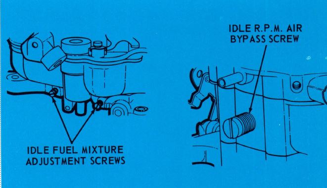
• Turn one idle mixture screw clockwise (inward) until the r.p.m. begins to drop; then, turn the screw counterclockwise (outward) 1/4 tum.
• Repeat the above step for the second idle mixture screw.
• Touch-up (slightly rotate in either direction) idle mixture screws for smoothest idle quality. The screws should be within 1/8 turn of each other. It may be necessary to readjust the idle air bypass screw to maintain specified idle r.p.m.
To adjust the idle air bypass screw (Pre-1970), the following procedure is suggested:
- Turn the idle air bypass screw clockwise (inward) until it lightly seats.
- Turn the screw counterclockwise (outward) 3-1/2- turns.
NOTE: Beginning with 1970 production, the idle air bypass is no longer used.
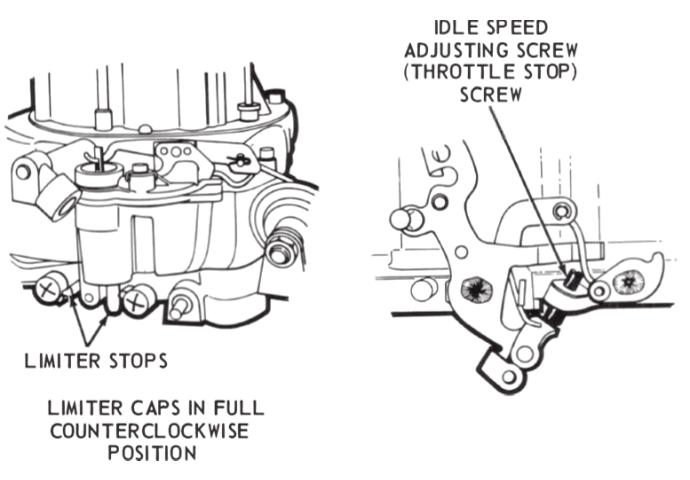
On carburetors in which the idle air bypass screw has been eliminated, a throttle stop screw has been added. This is the method by which the throttle plate is “cracked” open to establish the idle r.p.m., and a method employed by carburetor manufacturers for many years,
Also note in the above illustration, that the idle mixture screws use a plastic idle limiter. This limiter permits only about a 3/4 tum on the mixture adjusting screws. As you will recall, this reduces the possibility of an improper air-fuel ratio adjustment by unqualified personnel.