Adjustments – Air Bled Design
Float Setting
Invert casting and hold finger against float fulcrum pin retainer to assure fulcrum pin is bottomed in its guide slots. Measure the dimension as shown in specifications from surface of fuel bowl to the top of crown at center of each float (1955-56 at outer ends of float). To adjust bend lip of float.
NOTE: Never allow the needle to be pressed into seat when adjusting
Fast Idle Type I – Off Engine
Open. throttle valve slightly and hold choke valve fully closed to allow fast idle cam (in piston housing) to rotate to fast idle position. The dimension between lower edge of throttle valve and bore of casting should be as specified. To adjust, bend connector rod (C).
Type II – Off Engine
Place fast idle screw (A) on the index mark (or highest step) of fast idle cam and adjust the screw to the dimension as specified, between lower edge of throttle valve and edge of casting.
Type Ill – On Engine
With engine running at operating temperature, place, fast idle screw on step of cam as shown in specifications, then adjust fast idle screw to RPM specifications.
Unloader
Hold throttle valves wide open and close choke valve as far as possible without forcing. The dimension between top edge of choke valve and inner wall of air horn, should be as specified. To adjust (1955 and early 1956 carburetors) bend trip lever arm in housing; (late 1956 and later-see insert) bend unloader arm (B) on throttle lever.
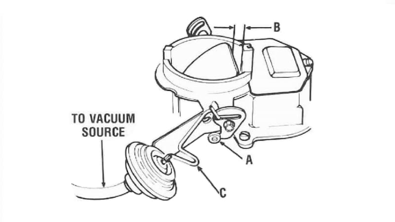
Choke Vacuum Kick – if Equipped
Press Diaphragm stem inward until diaphragm is bottomed on 1964 carburetors; 1965 and later, press diaphragm plunger (not stem) to bottom diaphragm to allow diaphragm stem internal spring to be compressed by extending the stem as choke valve is moved toward the closed position to obtain the proper dimension between top edge of choke valve and wall of air horn. To adjust to specifications, open or close the “U” bend of choke operating link.
NOTE: Optional method of bottoming diaphragm is to apply at least 10″ of vacuum from an outside source to diaphragm assembly.
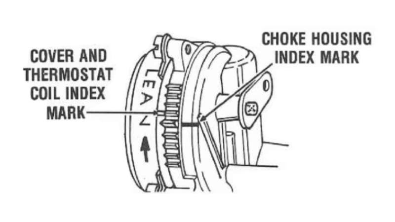
Automatic Choke
Carburetors equipped with integral (mounted on carburetor) choke. Rotate cover against spring tension until specified mark on thermostatic coil housing is aligned with mark on choke piston housing.
Pump
With throttle valves at curb idle and throttle connector rod (A) in center hole of throttle lever and inner hole of pump arm (unless otherwise noted in specifications).
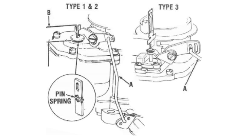
Type I
The dimension (B) from surface of casting to top of plunger shaft should be as listed in specifications. To adjust, bend connector rod (A)
Type II
The pin spring should be in center groove of plunger shaft to support vent valve for standard setting, unless otherwise noted in specifications.
NOTE: Change pin in accord with pump stroke. To adjust, bend ‘connector rod (A).
Type III
The retainer should be in center groove of plunger shaft. The dimension from the air cleaner gasket surface of air horn to top of plunger rod, should be as specified. To adjust, bend connector rod (A).
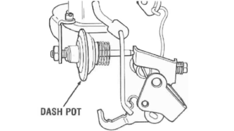
Dashpot – if Equipped
With throttle valves at curb idle, hold dash pot stem fully depressed. Loosen lock nut and adjust dashpot in or out of bracket to obtain 1/16″ between diaphragm stem and throttle lever tang. Tighten locknut.
Idle Speed and Mixture
Non-Emission Carburetors
Turn throttle speed screw in until throttle valves are opened slightly. Start engine and allow to warm up thoroughly. Turn mixture screws either way until the best idle is obtained. Readjust throttle speed screw to 450-500 RPM and again check mixture screws. 1968 and later carburetors see tune up decal in engine compartment for the proper RPM, or consult your motors manual.
Emission Carburetors
Follow idle mixture adjusting procedure as outlined in car manufacturer’s service manual. If not available, make temporary adjustment as follows:
- Check ignition timing.
- With engine at normal operating temperature, air cleaner installed where possible, and transmission in neutral.
- Turn throttle speed screw for speed of 500-550 RPM. For (C.A.P.) carburetors turn throttle speed screw to 700 RPM for Manual Transmissions, and 650 RPM for Auto Transmissions. For 1968 and later carburetors see tune up decal in engine compartment for specified RPM, or consult your motors manual.
- Turn idle mixture screws for the highest RPM using a tachometer.
- Readjust throttle speed screw if necessary.
- Turn each mixture screw clockwise (leaner) slowly, to obtain 10 to 20 RPM drop with each screw. Then turn each screw 1/4 turn counterclockwise (richer) for final adjustment.
Limiter Cap Installation – if Equipped
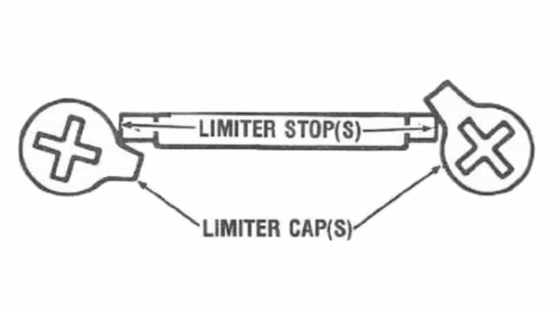
If the original limiter caps have been removed from the carburetor, the new service idle limiter caps must be installed after properly adjusting the idle speed and mixture screw to comply with existing State and Federal regulations regarding Exhaust Emissions. Soak caps in hot water for a few minutes to aid in installation. Place caps on mixture screw heads and press firmly using care not to turn mixture screws when forcing caps in place, with the tab in the maximum counterclockwise position against the limiter stops.

Adjustments – Solid Fuel Design
Float Setting
Hold float lip (A) against seated needle lightly while holding retainer (B) in bottom of guide slot. The dimensions between top of float (at center) and top of bowl should be as listed in specifications. To adjust remove float and bend lip (A).
NOTE: Never allow the needle to be pressed into seat when, adjusting. This will cause damage to the Viton tip and allow flooding.
Metering Rod
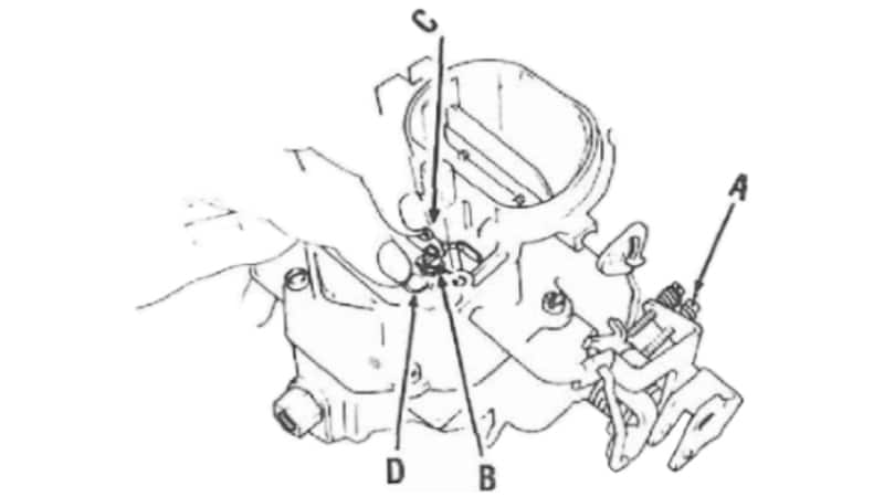
Back out the throttle speed screw to allow the throttle valves to close completely. Loosen the rod lifter lock screw (B). Fully depress the step-up piston (C) to bottom the metering rods. Apply light pressure on rod lifter tab (D) until the lip of tab contacts piston plate. Tighten screw (B).
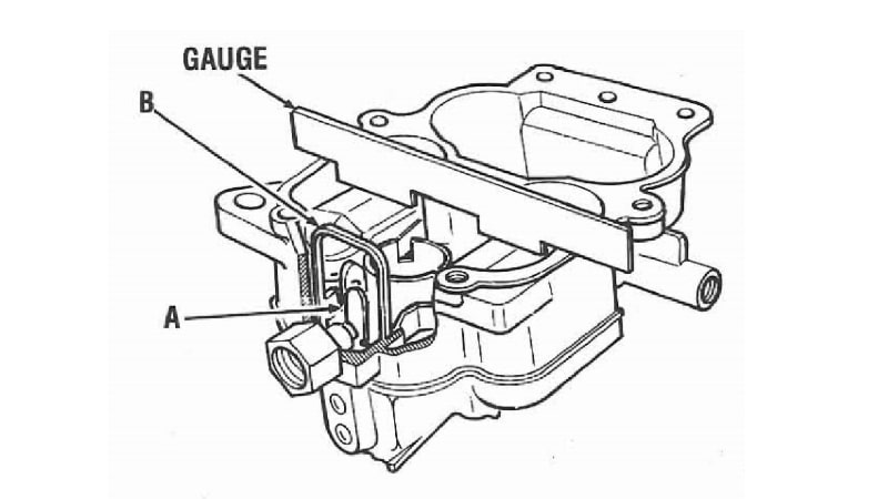
Pump
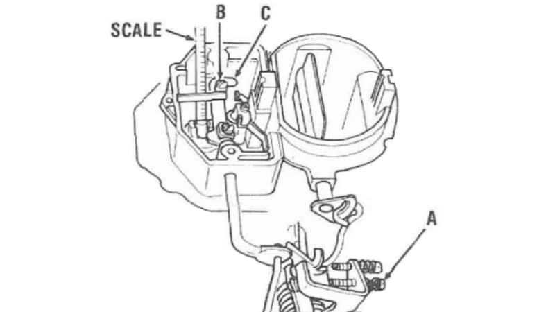
Turn curb idle screw two full turns clockwise after it just contacts stop, then hold throttle closed. Using a “T” scale, measure the dimension from the top of accelerator pump shaft to the top of bowl cover. It should be as shown in specifications. To adjust, loosen pump arm lock screw (B) and revolve pump arm (C). Tighten screw (B).
Bowl Vent – if Equipped
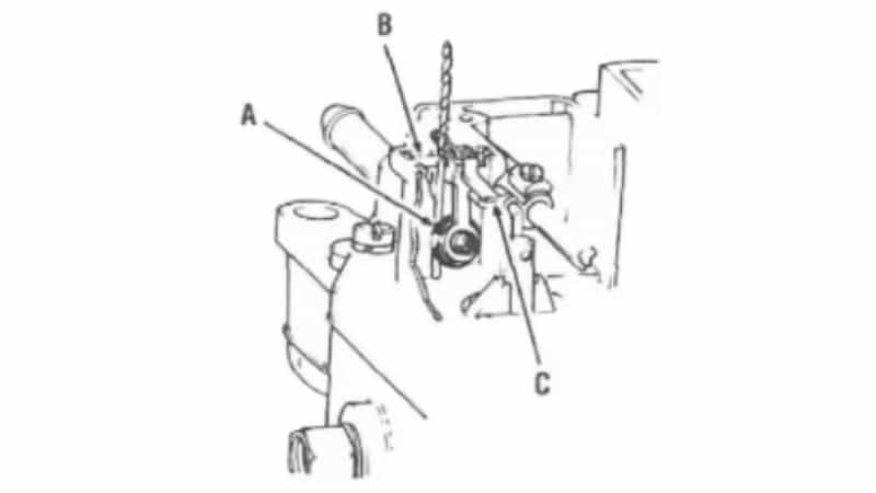
Turn curb idle screw two turns clockwise after it just contacts stop. With throttle held closed, a 3/32 drill should fit between the grommet seal (A) and its seat, with only a slight drag on the drill. Drill gauge must be positioned to touch the roll valve pin (B) while gauging the valve. To adjust, bend tang (C).
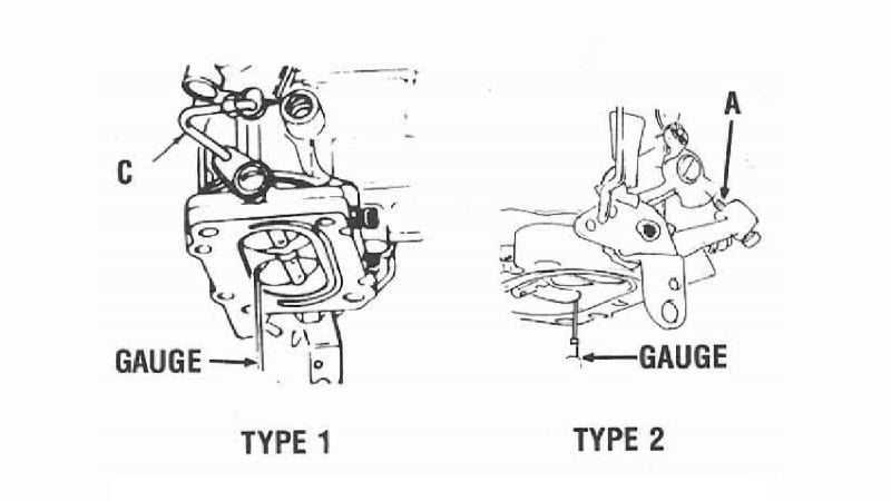
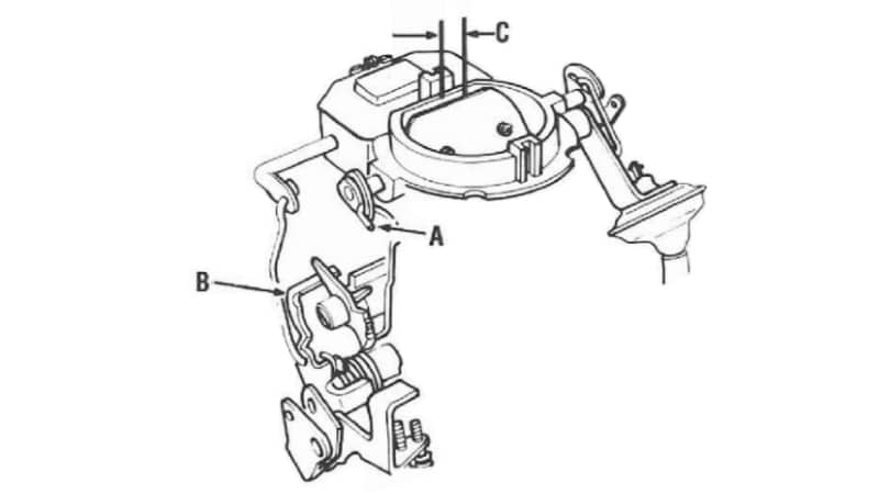
Fast Idle Cam
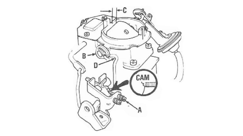
Place fast idle speed adjusting screw (A) on the second highest step of cam. Apply a light closing pressure on choke lever (B) to move the choke valve toward the closed position. The dimension (C) between the upper edge of choke valve and air horn wall should be as listed in specifications. To adjust, bend connector rod (D).
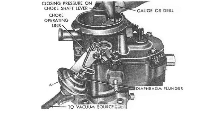
Choke Pull-off
Use an outside vacuum source to retract diaphragm stem fully. Apply a light closing pressure to choke lever (A), to move the choke valve toward the closed position as far as possible without forcing. The dimension (B) between the upper edge of choke valve and wall of air horn should be as listed in specifications. To adjust, open or close the “U” bend of connector rod at (C).
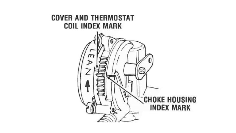
Automatic Choke
Rotate cover against spring tension until specified mark on thermostatic coil housing is aligned with mark on choke piston housing.
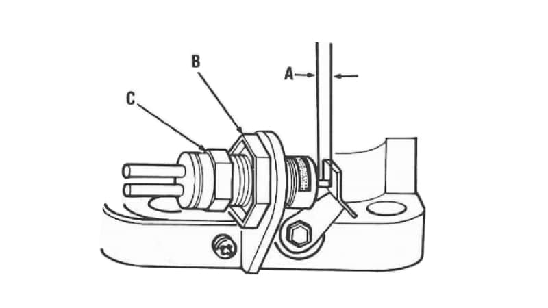
E.G.R. Dump Valve – if Equipped
With throttle valves held wide open and plunger stem fully depressed, the dimension (A) between operating lever and valve body should be 1/32″. To adjust, loosen locknut (B) on body and turn valve (C) in or out to proper dimension. Tighten locknut.
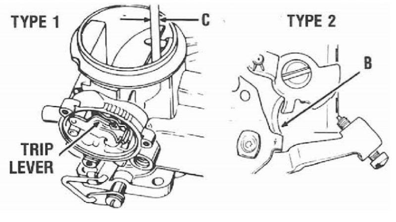
Unloader
With throttle in wide open position, apply light closing pressure on choke lever (A) to move choke valve toward the closed position. The dimension (C) between the upper edge of choke valve and wall of air horn should be as listed in specifications. To adjust, bend tang (B) on throttle lever.

High Altitude Adjustment – if Equipped
Turn screw (A) counterclockwise from seated position for high altitude operation. For sea level operation turn screw (A) clockwise to seal venturi cluster bleed cap (B). Refer to decal in engine compartment for proper specifications.
Idle Speed and Mixture
Use exhaust analyzer if available. If not available make temporary adjustment as follows:
- Refer to the “Emission Control Decal” in engine compartment for the proper engine RPM.
- With engine at normal operating temperature, choke fully open, air cleaner installed, automatic transmission in neutral, and air conditioner turned off.
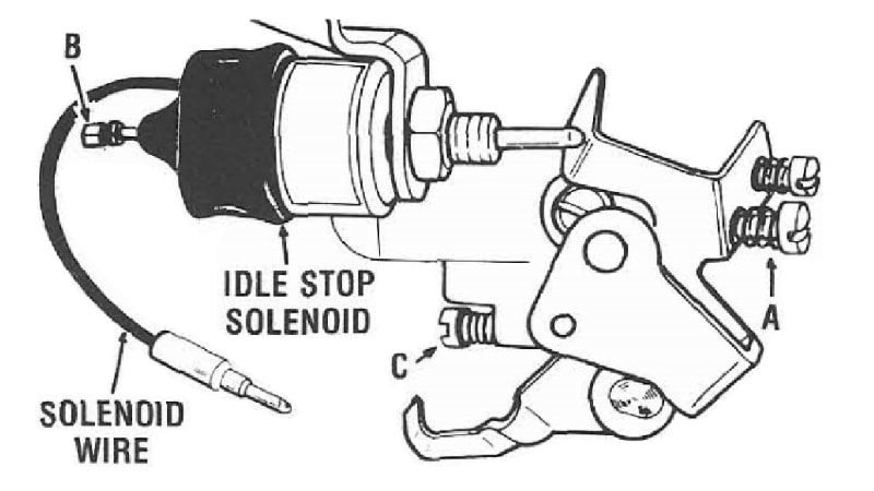
- Connect a tachometer and turn idle speed screw (A) or if equipped with the idle stop solenoid, turn solenoid speed screw (B) to the specified engine RPM, with the solenoid wire connected to energize the solenoid.
NOTE: The 1975 models equipped with the Catalyst Protection System will include a throttle solenoid positioner, and can be identified by a printed decal on the solenoid which states DO NOT USE solenoid or screw to set idle speed.
- Turn the mixture screws (C) counterclockwise (richer) until a loss if engine RPM is indicated on tachometer. Turn the mixture screws (C) clockwise (leaner) until the highest RPM is obtained, then continue turning clockwise until engine RPM starts to decrease. Turn the mixture screws counterclockwise (richer) until the lean best idle setting is obtained. Readjust speed screw if needed. If equipped with the idle stop solenoid, and with engine running, turn speed screw (A) inward until end of screw just touches stop, now back off one full turn to obtain low speed setting.
1977 and Later Idle Mixture And Speed Adjustment
Refer to decal in engine compartment for proper procedures and specifications. On models equipped with idle mixture screw plugs install replacement plugs.
Limiter Cap Installation – if Equipped
The new idle limiter caps must be installed, after properly adjusting the idle speed and mixture to comply with existing State and Federal regulations regarding Exhaust Emission.
Soak caps in hot water for a few minutes to aid in installation. Place caps on mixture screw heads and press firmly to seat, with the tab in the maximum counterclockwise position against the limiter stops.
Fast Idle – on Car
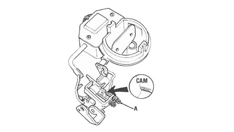
With the fast idle speed screw (A) placed on the second highest step of fast idle cam, turn the screw to obtain the RPM as listed in specifications.
Throltle Posltloner Solenoid – if Equipped
(Catalyst Protection System)
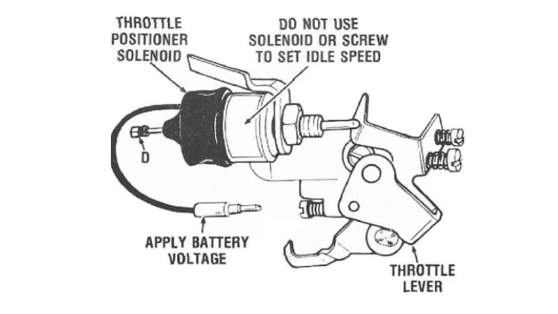
- Engine off, disconnect the solenoid wire and hold throttle wide open. Apply battery voltage with a jumper lead to solenoid wire. The solenoid stem should extend its full length and maintain its extended position. If it does not, replace unit. Remove the jumper lead from solenoid wire and release throttle.
- Connect a tachometer, start engine, again apply battery voltage, with jumper lead to solenoid wire. Adjust engine speed screw (D), if needed, to approximately 1500 RPM, allow time for O.S.A.C. valve to provide vacuum spark advance and engine speed to stabilize. Disconnect the jumper lead and reconnect the solenoid wire.
- Accelerate engine manually to approximately 2500 RPM and release throttle. Engine should return to normal idle.
Vacuum Throttle Posltloner – If Equipped
(Catalyst Protection System)
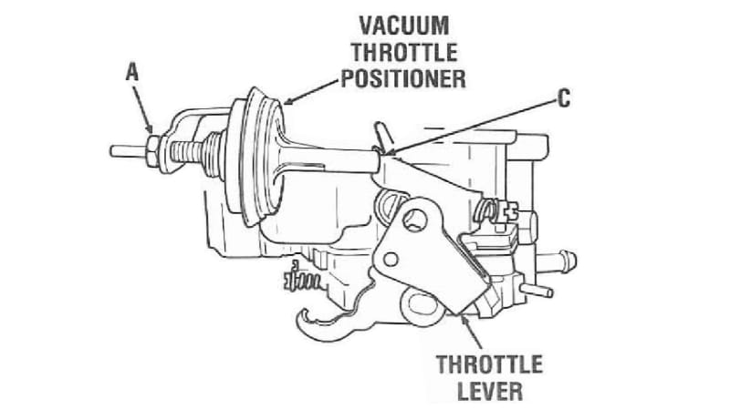
- Accelerate engine manually to speed of approximately 2500 RPM
- Loosen nut (A) and rotate vacuum throttle positioner until positioner stem just contacts at tang (C) on throttle lever. Release throttle, then slowly rotate the solenoid throttle positioner to decrease engine speed until a sudden drop in speed occurs (above 1000 RPM). At this point continue adjusting the vacuum positioner in the decreasing direction 1/4 additional turn and tighten nut (A).
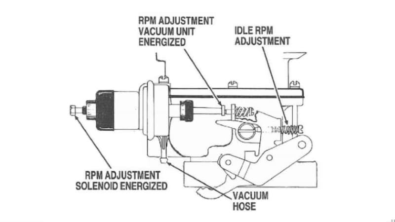
Sol-Vac
Three adjustments are required and must be made in the proper sequence.
- Disconnect vacuum hose from solenoid vacuum unit and plug hose. Also disconnect the electric wire to the solenoid. Adjust normal curb idle with R.P.M. screw.
- Using a hand vacuum pump, apply vacuum to the solenoid vacuum unit and adjust to the proper R.P.M. with the screw located on the throttle lever. Remove pump.
- Energize solenoid and adjust R.P.M. to specifications using the adjusting screw on rear of solenoid.
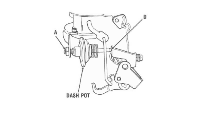
Dashpot – if Equipped
Loosen lock nut (A). Start engine and connect a tachometer. Position throttle lever to 2500 RPM. Adjust dashpot until the stem just contacts tang at (D) on throttle lever. Tighten nut (A). Check to make sure engine returns to idle after making this adjustment.
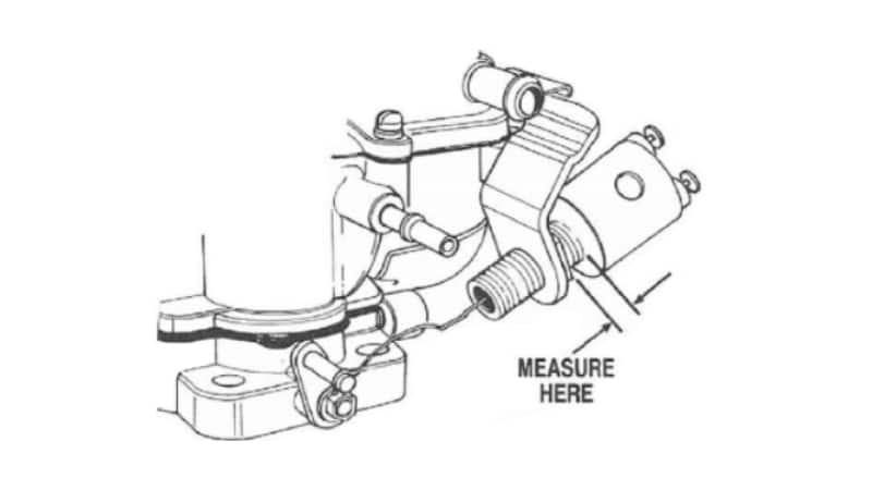
Transducer – if Equipped
To adjust the transducer, measure distance between outer portion of transducer and transducer mounting bracket. Turn transducer clockwise or counterclockwise to obtain distance as specified.