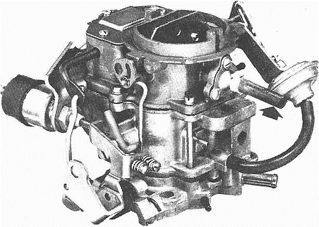
The model BBD is a BB design, dual carburetor with low overall height. Accessible adjustments and removable subassemblies.
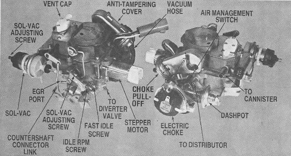
It has been supplied in both 1 ¼ and 1 ½ inch S.A.E. flange sizes. Five conventional circuits are used. They are:
- Float circuit
- Low speed circuit
- High speed circuit
- Pump circuit
- Choke circuit
All BBD carburetors prior to 1974 are of the air-bled design incorporating downhill nozzles. 1974 and later models are of solid fuel design with uphill nozzles. The solid-fuel design provides more precise fuel metering to meet emission standards while still maintaining maximum response and drivability. For increased life and smooth operation, the solid fuel design uses a Teflon-coated throttle shaft.
Circuits
Float Circuit
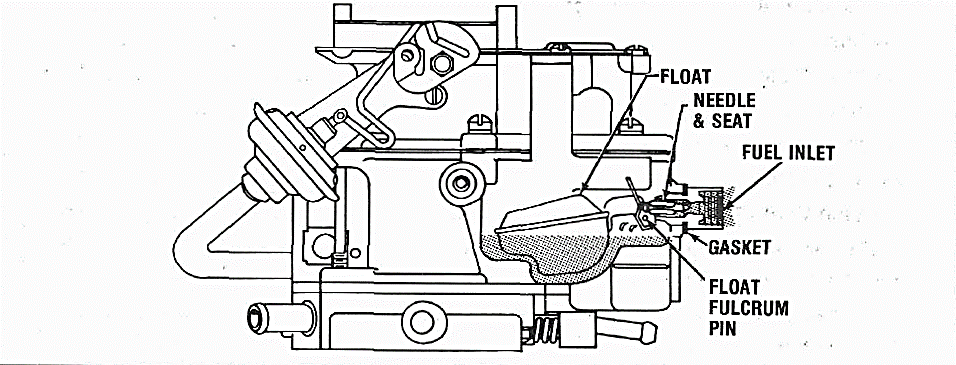
All fuel enters through the fuel inlet fitting in the bowl. The fuel inlet needle seats directly in this brass fitting and is controlled by the twin or dual floats which are hinged by a float fulcrum pin. The fulcrum pin is held in position by the “horseshoe” retainer. The twin floats follow the contours of the fuel bowl and are designed to provide a stable fuel supply under all conditions. Only a minimum of fuel is maintained in the carburetor, preventing excessive fuel evaporation. This tends to improve warm engine starts.
The float circuit must constantly maintain the specified fuel level as the other circuits are calibrated to deliver the proper mixture only when the fuel is at this specified level. When the fuel level in the bowl drops, the float also drops permitting additional fuel to flow past the inlet needle into the bowl.
The bowl is vented to the inside of the air horn. The bowl vent is calibrated to provide proper air pressure above the fuel at all times. To assure a positive seal, always use a new bowl cover gasket when reassembling. An air leak at this point can result in a mileage complaint.
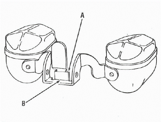
Float Adjustment
Remove float to adjust. NOTE: To obtain his proper alignment it may be necessary to bend the float lip at either or both arrows “A” and “B”. CAUTION: Never allow the needle to be pressed into the seat when making the adjustment as this might damage the viton tip.
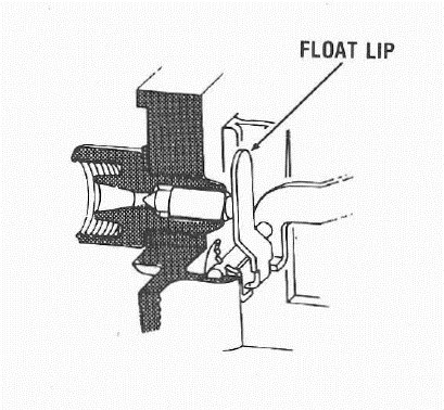
After the float adjustment has been made and set to the manufacturer’s specifications, the float lip must be in the vertical position with the needle lightly seated.
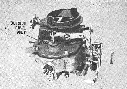
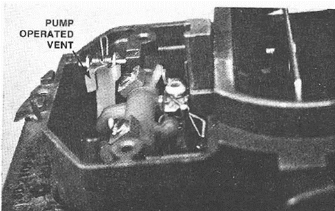
Venting the System
The BBD carburetor also uses an outside bowl vent that opens at the closed throttle position. When the engine is turned off, underhood temperatures increase causing vapors to rise from the fuel in the bowl. The outside vent improves starting characteristics as it prevents vapors from entering the bore of the carburetor by way of the inside vent.
Bowl vapor vent adjustment must be to specifications. If the valve does not open to specifications with throttle valves seated, bowl vapors cannot escape freely and this may cause “hard-hot-starting.” if it opens too far, or hangs open, it will allow an external vent to the bowl, resulting in poor mileage.
Emission Laws effective in 1971 required all outside vents to be routed to a canister to prevent evaporative emissions.
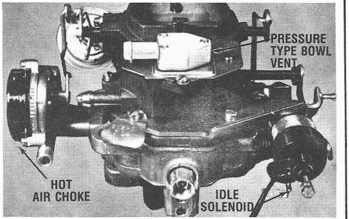
Two Way Bowl Vent
To meet evaporative emission regulations. Late-model BBD’s use a solenoid-controlled two-way bowl vent.
When the ignition switch is in the off position. The spring-loaded diaphragm forces the puck valve to its upper position, thus closing the inside carburetor vent and opening the canister vent. When the ignition switch is turned on, the solenoid is energized moving the puck to its downward position. Thus closing the canister vent and opening the inside carburetor vent.
If the solenoid should fail, venting to the carburetor fuel bowl would be by way of the canister. This change in bowl pressure would affect drivability. An increase in bowl pressure causes a rich condition. Lowering bowl pressure results in a lean condition.
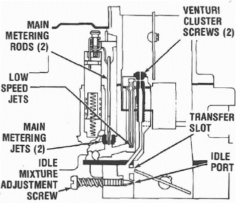
Low Speed Circuit
Fuel for idle and early part throttle operation is metered through the low-speed circuit.
Fuel enters the idle and high-speed wells through the main metering jets. The low-speed jets measure the amount of fuel for idle and early part throttle operation. The by-pass, idle air bleeds, and economizers located in the venture attaching screws are carefully calibrated and serve to break up the liquid fuel and mix it with air as it moves through the passage to the idle ports and idle adjustment screw ports. Turning the idle adjustment screws toward their seats reduces the quantity of fuel mixture supplied by the idle circuit.
The idle ports are slot-shaped. As the throttle valves are opened, more of the idle ports are uncovered, allowing a greater quantity of fuel and air mixture to enter the carburetor bores.
The by-pass, idle air bleeds, economizers, low-speed jets, idle ports, idle adjustment screw ports, as well as the bores of the carburetor flange, must be clean and free of dirt and carbon. Obstructions will cause poor low-speed engine operation.
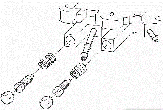
Idle Adjusting Screw
The idle bleed is into the bore of the carburetor on the atmospheric side of the closed throttle valve. The amount of bleed varies with throttle position.
Idle adjusting screws are used for trimming the idle mixture to individual engine requirements for satisfactory idle.
Emission Laws require the use of idle adjusting screws with limited adjustability. This allows for proper idle adjustment while assuring the emission limits will not be exceeded.
One design uses an Allen screw as a stop as it makes contact with the shoulder on the recessed portion of the idle adjusting screw.
On the flow test, the idle adjusting screw is turned in the counterclockwise direction to the mean rich limit. The Allen screw is then turned in against the recessed shoulder of the idle adjusting screw. The Allen screw hole is then filled with a lead plug.
Another version uses an idle adjusting screw which is completely recessed in the flange of the carburetor.
After final adjustment, it is sealed with a lead plug.
The upper adjusting screw is an air adjustment screw and adjusts the mixtures for both bores.
This air adjustment screw has left-handed threads. Turning the adjusting screw counterclockwise moves the screw inward to richen the air-fuel mixture.
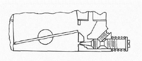
Adjustable Off-Idle Air Bleed
Some older BBD models use an adjustable off-idle air bleed which is adjusted during flow test. This adjustment should never be changed as it cannot be adjusted in the field.
The purpose of the “adjustable off-idle air bleed” is greater control of the air-fuel ratio at flow rates above curb idle, resulting in a substantial reduction in hydrocarbons.
The circuit consists of an adjustable spring-loaded ball check valve located in an air passage to the low-speed circuit.
Closer calibration can be attained by being able to adjust the idle fuel mixture at two different points in the air-fuel ratio curve.
The air bleed valve is set to open at an idle port vacuum of 7 to 12 inches of water which is slightly above the three to four inches at curb idle.
When the throttle is opened slightly, the lower pressure at the idle port opens the air bleed valve to control the air-fuel ratio.
If the rate of acceleration reaches a certain maximum, the vacuum at the idle port will drop below the 7 to 12 inches of vacuum allowing the air bleed valve to seat. This enrichment of the air-fuel mixture is desirable for a high rate of acceleration.
As the bleed port is below the closed position of the choke valve. Air will not enter the air bleed valve until the choke valve is partly open, thus making the automatic air bleed inoperative during the early stages of engine warm-up.
The air bleed valve will open on deceleration from high speed to prevent rich mixtures.
The “adjustable off-idle air bleed” is also used on some AVS models.
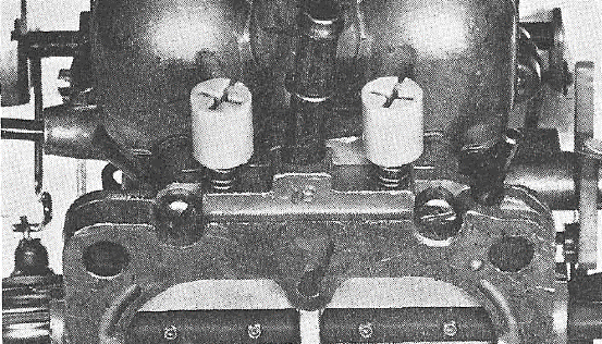
Idle Limiter Caps
All late-model carburetors use idle limiter caps to prevent over-rich idle adjustments.
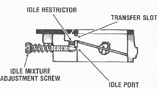
Idle Restrictors
In addition to limiter caps, some late models use idle restrictors located in the throttle body. The purpose of the restrictor is to limit the maximum air-fuel enrichment available at idle.
Tamperproof Mixture Screws
Same 1979 and later model carburetors will use the hidden “tamperproof idle mixture screws.” These screws are adjusted and sealed at the factory. Adjustment of the sealed idle mixture screws should be performed only when the carburetor will not meet specifications or when a major carburetor overhaul is necessary.
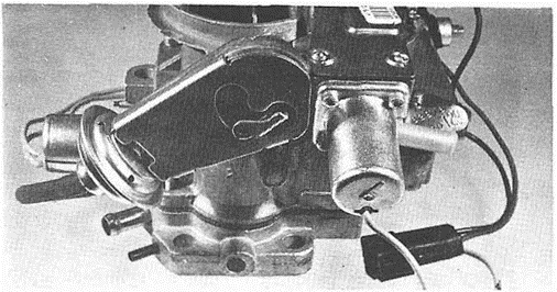
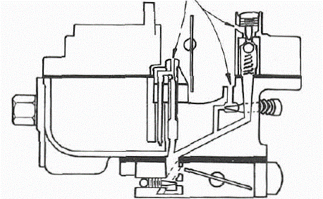
Idle Enrichment System
Some models use an I.E.S., “Idle Enrichment System,” to improve cold engine performance at the initial starting of the engine. Along with this carburetor circuit or system, an electronic timer and vacuum solenoid valve are also used. The timer energizes the solenoid valve during starting and for 35 seconds after start.
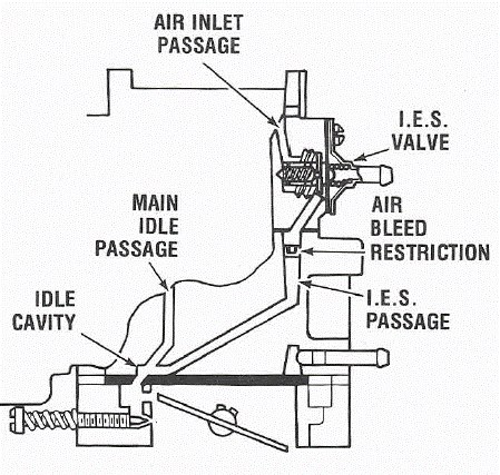
When the solenoid is energized it cuts off the EGR system which eliminates any exhaust gas recirculation from taking place. Secondly, it applies manifold vacuum to the idle enrichment diaphragm when the engine coolant is below a predetermined temperature. The manifold vacuum overcomes the spring tension and pulls the diaphragm away from the seat and valve, thereby allowing the valve to seat closing off the air passage.
Cutting off the air supply enriches the idle mixture which allows more fuel to be delivered during starting and for 35 seconds after start. After the 35 second delay period, the electronic timer de-energizes the solenoid valve which allows the EGR system to function and also cuts off the manifold vacuum to the idle enrichment diaphragm.
The spring then pushes the diaphragm against the valve and seat assembly causing the valve to unseat. This in turn allows air to flow through the system and a normal air-fuel ratio to be delivered to the cylinders. The purpose and results are improved hot engine starting by delaying the EGR for 35 seconds and improved cold engine performance after starting by initiating idle enrichment for 35 seconds.