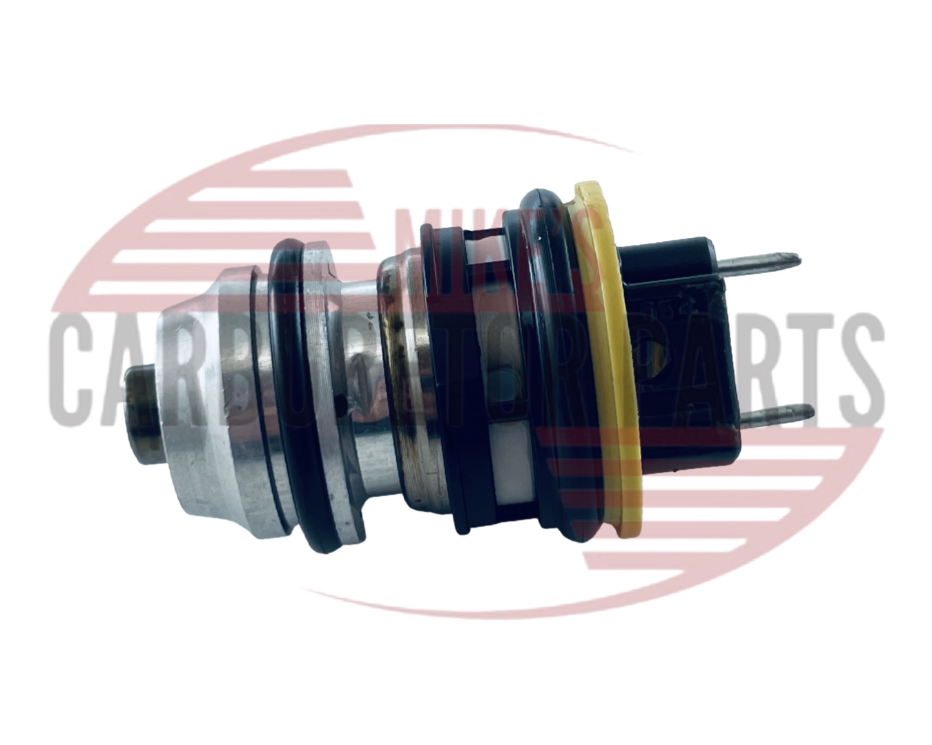
Mike’s Carburetor

Featured

Welcome to Mike’s blog. I hope you find my articles helpful as well as informative. I welcome comments on any of my articles. You might also want to sign up for my email notification so that you are notified any time a new article is added.

We have a ton of technical information for just about any carburetor and new information is being added on a daily basis. Check back again.

For all of your carburetor needs, please visit Mike’s Carburetor Parts.

Thank you for visiting

Mike

The Truth About NOS Carburetor Kits

NOS, New Old Stock, which means a part has been sitting around for several years and may not be produced anymore. Some refer to NOS as new old original equipment parts, but NOS can also include non original aftermarket parts.

You will find some NOS and some used parts in our web store, but you will not find any NOS carburetor kits. We only sell kits that are currently, or recently being manufactured. We do sometimes get a part, or kit that has been discontinued. This isn’t the same as NOS because while the part is new, it isn’t necessarily old. Some discontinued parts may have been sitting around for a few years, maybe even 5, while NOS parts have probably been sitting around for 20, or more years.

Why don’t we sell NOS carburetor kits? NOS kits were manufactured for gasoline much different from today’s gasoline. Gaskets were more porous and made of materials not conducive to today’s gasoline. When I refer to today’s gasoline, I’m mostly referring to the ethanol that is added to gasoline. Most gaskets in our carburetor kits, are generally coated with black nitrate which helps keep gasoline from seeping through (another ethanol side effect). NOS carburetor kits usually will not have this feature. Gaskets that have been sitting around for 20 plus years will also be dried out, making them brittle and not pliable. This makes sealing our already worn carburetor surfaces even harder. Any rubber parts included in a NOS kit would surely be suspect. The rubber is probably not as pliable as it should be and in most cases not up to today’s fuel blend. Leather accelerator pumps found in some NOS kits would be OK. Just be sure to add a few drops of oil to the leather before installing. On the other side, old NOS kits that include rubber accelerator pumps should be avoided, or at least the pump not used. Older accelerator pumps were not made for today’s fuel and can easily fail. I’ll be the 1st to admit that even today’s newest methanol resistant pumps can fail if subjected to enough ethanol, but at least they give you a fighting chance.

On the plus side of the NOS carburetor kit, they sometimes include parts not available in today’s kits. An example are the old Carter master rebuild kits made in the 50′s. Carter made a carburetor kit for almost every car and there was little consolidation unlike in today’s world. Those kits often had jets, linkage and levers that are no longer available. Buy the NOS kits for these parts and throw away the gaskets, pump, needle & seat.

There is a place for old NOS carburetor kits and that is when a new kit is not available and the NOS kit may be the only solution, but why not give your classic the best you can get. Rebuild your carburetor, using high quality parts that are currently being produced and you will have less carburetor problems and leaks.


Marvel Schebler Jet Removal

Complete Rebuild DVD Marvel Schebler DVD
Marvel ScheblerSchebler Customer question.

Can you give me ideas on how to
remove the main nozzle for a Marvel Schebler TSX-530 Type C
carburetor?  According to the manuel it unscrews from the
bottom.  I assume that the main jet and the nozzle are one
piece.  I haven’t tried beating on it or cranking on it yet.
I don’t want to screw it up until I know that I can replace it.
Have replacement parts?
My main problem is that the idle
pick-up hole (the second one from the right of the main throat in the
first pic.  The first one I think is air vent to the bowl.) is
clogged.  I’ve tried using a copper wire, air pressure, and
solvent, but can’t unplug it.  Consequently it won’t idle without
choking.
Yes, this jet does remove. You can try using a brass drift punch on the
end and hitting it a few time with a hammer. Don’t get over zealous.
Penetrating oil might help. Be sure to clean the carburetor after
because anything like WD40 will react with ethanol and eat the gaskets.Try applying heat to the steel around the jet. That gets me out of
trouble a lot of times.

Whatever you do, be carefull about trying to turn the jet with a screw
driver, having it slip and rounding off the edges. You will never get
it removed if that is done.


Carter W-1 Throttle Shaft Leaking Fuel

I get questions about fuel leaking at the throttle shaft often. This time it is a question about the Carter W-1 carburetor leaking fuel past the throttle shaft.

The cause is simple. There is too much fuel entering the carburetor throat. We call it flooding. The fuel is dripping on the throttle plate and running down the shaft. No, the  throttle shaft should not be so tight that fuel can’t get past it. The shaft must be free enough to allow it to return easily when letting up on the gas. There is always some sort of gap between the shaft and the throttle body.

Flooding is caused by too much fuel entering the carburetor and flooding over and there is a short list of things that will cause this, but with the W-1, the most likely cause is a dirty carburetor. Carburetors are the ultimate fuel filter and the W-1 is especially good at it and I suspect it is because there usually isn’t any fuel filter between the gas tank and the carburetor.

I once had a W-1  that I had rebuilt returned to me because it ran great for a few miles, then started to run very rough, coughing and sputtering. When I took the top off I was amazed at how much crud was in the float bowl. There was literally no room for any gasoline. It seems the mechanic replaced the fuel sending unit at the gas tank, which loosened up a lot of rust and it all ended up in the carburetor.

Cleaning and replacing the parts included in our carburetor kit will most likely take care of a flooding problem caused by dirt.

Other possible causes might be a bad float. Be sure to test it by placing it in hot (pre boiling) water and look for any bubbles. Another possibility that would be low on the list would be a fuel pump putting out too much pressure. This might be especially suspect if you recently replaced the pump. Find the specifications for your vehicle and test the pressure and the volume.

Back to the throttle shaft. Test it by spraying some carburetor cleaner around the shaft and see if the RPM fluctuates at idle. Being able to wiggle the shaft back and forth more than say 1/32″ could be an indication the shaft is worn.

So, bottom line is that you have to think about the cause of a leaky shaft and not be too quick to blame the shaft itself. Actually, I have found the W-1 stands up well as compared to other types of carburetors.


Rochester 1 Barrel Main Discharge Repair

The Rochester B carburetor can have a couple of different types of main discharge check ball assemblies as shown in Illustration 1. The float bowl on the left is our main concern here. You can watch the how to video below, or read on to get the same information.
Watch a video about how to repair this.
 

Rochester B


Illustration 1

Rochester BThe float bowl on the right is the more popular type of discharge. It assembles with a check ball, spring, then a T to hold it in as in Illustration 4 & 5. The float bowl on the left and the bowl in Illustration 2 has the same type of assembly except instead of a T, there is a slotted brass plug. You may mistakenly think that it is a threaded plug because of the slot, but it looks more like a piston (no threads), which fits snugly into the hole, holding the spring down. As you can see in Illustration 3, the plug is slotted which allows fuel to flow through.


Illustration 2

Rochester B Repair


Both types of discharge need to be cleaned out, or you could have acceleration problems. The problem with the brass plug type is that they are often frozen into the bowl and when you try to remove it with a screw driver it can break and often does. One way to get the plug loose might be to heat up the bowl around it, but be careful as you could warp the float
bowl. I always try to remove the plug so that I can use it again, only because I tend to like things original, but I don’t lose any sleep when
they do break. Do whatever you can to get it out. You can try using a wire with a small hook on the end to pull it out, or use a screw driver to turn it back and forth until it is loose enough to fall out.


Illustration 3

Rochester Main DischargeWhen the plug does break, throw it away and use the T that comes with the carburetor kit that we sell. Place the check ball (the bigger one), in the hole 1st, then the spring and then the T. You will have to make a couple of slots into the float bowl for the T to sit down into. Use a dremmel tool, or something similar. It doesn’t have to be anything fancy. The goal is to simply get the T to fit into the hole flush with the float bowl top. Illustration 4 is what the float bowl would look like with the T inserted. Check out Illustration 5 to see what the sequence is for the T, spring & check ball.


Illustration 4
Rochester B


Illustration 5
Rochester

Holley 1940 Throttle Body Bushing Replacement

When the Holley 1940 carburetor throttle shaft gets .010 or more of wear, it is time to add bushings to the throttle body. Without a run-out mike this might be difficult to measure, so estimate anything over 1/32″ in sideways action. When the throttle shaft is too loose it will cause a vacuum leak, which will make the engine idle rough. Besides measuring you can test this situation by spraying carburetor cleaner around the throttle shaft while the engine is running. If the rough idle smooths out, then you need to re-bush.

Holley 1940 Bushing

If you don’t think you have the expertise to tackle a job like this, then you should take it to a machine shop, otherwise here is one way you can accomplish this without having to have a lot of sophisticated machinery.

The bushings required can be found in our Holley 1940 carburetor parts catalog.You will need to order two bushings.

Carefully ream out the hole so that the new bushing will fit. Use an expandable reamer HS 6A. It needs to expand to at least .345″. You want to ream the hole until the bushing fits into it tightly. Not so tight that you have to beat it in, but it should take some pressure. If you get it too tight and have to beat it in place, the bushing will reduce down and the throttle shaft might not turn as freely as it should. You can add a bit of JB Weld around the outside of the bushing to make sure it stays put, but with the right fit you will not have to do this. Once you get the bushing in grind down anything that is sticking out so that the bushing is flush with the throttle body.

That is it. Replace the throttle shaft and you are on the way. Take your time, because it doesn’t take much of a mistake to ruin the throttle body.

Adjustments for 1968 Pontiac Tempest & Firebird 250″ engine.

The Rochester BV carburetor is a one barrel downdraft carburetor with a divorced choke. Divorced meaning the choke thermostat is mounted in the manifold, connected to the carburetor with a choke rod.

Adjustments

Idle Speed & Idle Mixture

Turn the idle mixture screw in (clockwise) until seated, lightly. Scoring of the idle mixture screw is caused by being turned in to hard. Turn the screw back out (counter clockwise) about 5 turns.

  • Bring the engine to operating temperature.
  • With the solenoid engaged adjust the stop screw until the engine is running at 610 rpm.
  • Turn the idle mixture screw in until the engine speed is 600 rpm.
  • Disconnect the stop solenoid so that it is de-energized. The throttle valve will close until the stop screw contacts the low step of the fast idle cam.
  • Adjust the stop screw until the engine reaches the idle speed of 500 rpm.

The fast idle adjustment is not necessary. This setting is adjusted automatically when the above is completed.

Note: A carburetor in need of a rebuild can sometimes be identified by the idle mixture screw not making any difference in engine rpm when being adjusted. A rough idle after doing the above steps can also indicate a dirty carburetor assuming the electrical system is up to par.

How the Holley 847 Carburetor Works

Holley 847

Figure 1

Holley 847

Figure 2

Holley 847

Figure 3

Holley 847

Figure 4

Holley 847

Figure 5

Holley 847
Figure 6

Holley 847 Carburetor Kit

Purpose of the Carburetor

The carburetor delivers a combustible mixture of fuel and air to the intake manifold of the engine. It automatically controls the amount of fuel being mixed with the air to meet changing engine operating conditions, delivering a greater amount of fuel when high power output is required and less fuel for economical cruising.

 The Engine

 The effect of the engine upon the carburetor may be compared with that of a suction pump. As each piston moves downward on its intake stroke, a partial vacuum is created in the cylinder. This draws the fuel air mixture from the carburetor and intake manifold into the cylinder through the opened intake valve. fig 1

If an engine was intended to run at only one speed and load, its carburetor could consist of a simple nozzle spraying fuel from a gravity feed tank into the intake manifold. fig 2. Once the rate of flow of the fuel was adjusted to give a satisfactory mixture, no change would be necessary.

The Venturi

Since the operating conditions of an automotive engine are subject to constant change, the carburetor must automatically adjust the fuel flow
for these changes. The venturi in the carburetor provides a force which controls the fuel discharge in the normal cruising speed range.

The venturi is a specially designed restriction which causes air to momentarily increase its speed while passing through it. This creates a drop in air pressure, commonly called vacuum, in the venturi. As the speed of the air flow in the carburetor increases with an increase in engine speed, the vacuum in the venturi becomes correspondingly greater. This vacuum in the venturi is utilized to pull the required amount of fuel from the fuel supply in the carburetor, as will be described later.

The relationship of air pressure to velocity can be illustrated by a simple experiment. Hold the edge of a sheet of paper to your lower lip, allowing the rest of the sheet to hang limp. Blow across the top of the paper and you will notice that it rises. Air in motion over the top of the paper exerts less pressure than the normal atmospheric pressure of the stationary air under the paper, and the difference in pressure moves the paper upward. You will also notice that, as the speed of the air is increased, the pressure above the paper is decreased correspondingly, moving the paper still higher. Differences in air pressure similar to the example given here provide the basic force for carburetor operation.

 The Main Metering System

Figure 4

The main metering system, which provides fuel for cruising speeds, is a continuous passage from the float chamber to the main discharge nozzle. The main discharge nozzle is located at the center of the venturi in the area of the greatest vacuum. The float chamber, containing fuel, is vented to the carburetor air inlet, where the air pressure is practically atmospheric, being only slightly affected by the restriction of the air cleaner. The air pressure on the fuel in the float chamber is greater than the air pressure in the venturi. This difference in pressure forces fuel through the main metering system. The fuel flows from the float chamber through the main metering jet and into the bottom of the main well. It is drawn from the main well through an angle channel and is discharged from the main discharge nozzle.

The main metering system delivers an economical mixture of approximately one part of fuel to sixteen parts of air by weight.

These proportions may vary slightly for different engines due to their design, but the figures are satisfactory for purposes of illustration. The metering, or measuring, of the fuel flow is accomplished primarily by the main metering jet, the smallest fuel restriction in the main metering system.
Air Bleeds

Figure 4

The fuel supplied to the cylinders must be vaporized to burn completely during the power stroke of the piston. Fuel which enters the cylinders in liquid form burns too slowly and is wasted. Vaporization of the fuel discharge is aided by air bleed passages which introduce air into the stream of fuel before it is discharged. This emulsion of fuel and air responds more readily to any change in vacuum and vaporizes more efficiently when it is discharged.

 The Throttle

Figure 4

The throttle plate in the carburetor bore governs the power output of the engine by regulating the amount of fuel air mixture admitted to the intake manifold. It is controlled by the driver of the vehicle through the accelerator pedal.

 The Float System

Figure 4

The float system provides a constant supply of fuel in the float chamber for use by the fuel metering systems in the carburetor. Fuel under pressure from the fuel pump enters the float chamber through the fuel inlet needle valve. The float, which rises or lowers with the fuel level in the float chamber, controls the fuel inlet needle valve to admit only enough fuel to replace that being used.

When the engine is started, the fuel level in the float chamber begins to drop as fuel is used. The float is lowered, opening the fuel inlet needle valve and allowing more fuel to enter the float chamber. When the fuel in the float chamber rises to a specified level, the needle valve will restrict the flow of fuel into the float chamber so that only enough fuel is admitted to replace that being used, thus maintaining a constant fuel level. Actually, the fuel level will drop slightly as engine speed increases, since the needle valve must be opened more to meet the increased fuel demands of the engine.

 Low Power Operation

 At idle and low speeds, the air flow through the carburetor is greatly reduced and the vacuum in the venturi is too weak to draw fuel from the main metering system. The nearly closed throttle plate restricts the flow of air into the engine, resulting in a strong manifold vacuum.

 The Idle System

Figure 5

During low power operation, the pressure difference between the manifold and the float chamber forces fuel through the idle system. The fuel flows through the main metering jet into the bottom of the main well, where it is drawn upward through the idle tube. The narrow tip at the bottom of the idle tube is a calibrated restriction which primarily meters the flow of fuel in the idle system.

 Idle Mixture

Figure 5

Fuel distribution in the manifold is usually not as efficient at idle and low speeds as it is in the normal cruising range. The idle system delivers a rich mixture so that all cylinders will receive enough fuel. The mixture at idle can be adjusted to meet the needs of the individual engine by setting the idle adjusting needle. The idle adjusting needle controls the amount of fuel discharged at the idle discharge hole only. This determines the mixture ratio delivered at idle.

 Off Idle Operation

Figure 5

When
the throttle plate is moved past the idle transfer hole, exposing it to manifold vacuum, fuel is also discharged from this hole. Otherwise, the idle system functions the same as is explained in paragraph 9. As the throttle plate is opened wider and engine speed increases, the main metering system begins to supply fuel and the idle system flow is reduced. As the cruising speed range is reached, the main metering system takes over completely, supplying all the fuel needed for engine operation. The two systems are engineered to provide a smooth gradual change with not flat spots in off idle performance.

 High Power Operation

 When the load on the engine is great enough to require high power output, the mixture must be enriched to approximately one part of fuel to twelve parts of air by weight. This mixture, while not as economical as the one to sixteen ratio delivered for normal cruising, enables the engine to develop full power output at all speeds above the idle range. The power enrichment system automatically supplies the added fuel only when it is needed.

 The Power Enrichment System

Figure 6

The power enrichment system is actuated by manifold vacuum, which gives a true indication of the power demands placed on the engine. When a high load is placed on the engine, an above normal opening of the throttle plate is necessary to maintain speed. The open throttle plate offers less resistance to engine suction and the manifold vacuum is reduced.

 Manifold vacuum is transmitted through the vacuum passage in the carburetor to the piston in the vacuum chamber. The vacuum acting on the piston at idle and normal cruising speeds is strong enough to hold the piston up in the vacuum chamber, compressing the spring on the piston stem. When high power demands reduce manifold vacuum beyond a predetermined point, the spring expands to force the piston and stem assembly down. This

depresses the pin in the center of the power valve, opening the valve. Fuel from the float chamber flows through the center of the valve and out calibrated holes in its side. These holes meter the fuel flow to provide the necessary enrichment. The fuel flows through a passage to the main well where it joins the fuel flow in the main metering system, enriching the mixture for full power. In the dual carburetors used on V type engines, one power valve supplies fuel to both main wells. A restriction is added in the fuel passages leading to the two main wells to assure that they both recieve the same amount of fuel from the power valve.

 Acceleration

 When the engine is accelerated, there is a slight lag in response of the previously described systems. Gasoline, being heavier than air, is more difficult to move. The air flow responds almost immediately to a suddenly opened throttle, but there is a brief interval before the fuel in the narrow passages can gain speed and maintain the fuel air balance. The accelerating pump system operates during this period, supplying the necessary fuel until the other systems can again provide the proper mixture.

 Accelerating Pump System

Figure 7

The accelerating pump is linked to the throttle operating mechanism so the pump will operate when the throttle opening is increased upon acceleration. When the throttle is closed, the pump piston is up in the well and fuel enters the well through a passage from the float chamber. The pump inlet ball check valve permits fuel to enter the pump well but prevents a reverse flow of fuel when the pump is operated. The pump
operating rod, which is linked to the throttle lever, moves downward as the throttle is opened. The horizontal arm at the top of the pump operating rod slides down in the slot in the pump piston stem, compressing the pump spring. The spring presses the pump piston down, forcing fuel through the passage to the pump discharge needle valve. The fuel, under pressure from the pump piston, unseats the pump discharge needle valve and flows past it and out the pump discharge nozzle. The pump discharge needle valve closes the passage when the pump is not discharging fuel. In addition to preventing fuel from being drawn from the pump well by the suction of the airstream at high speeds, the needle valve seals the passage so that air will not be drawn into the system when the throttle is again closed and the pump piston is raised to draw in another charge of fuel. The narrow passage in the pump discharge nozzle is a calibrated restriction which provides a resistance to the flow of fuel. The resistance opposes the pressure of the pump spring to prolong the discharge for smoother engine operation.

 Cold Starting

 When starting a cold engine, much of the atomized fuel from the carburetor condenses to a liquid on contact with the cold surfaces of the intake manifold. The fuel in liquid form burns too slowly in the cylinders, causing loss of power and stalling.


The choke provides a means of enriching the fuel discharge so that enough vaporized fuel reaches the cylinders to permit the engine to run smoothly during the warm up period.

 The Choke

Figure 8

Closing the choke plate in the carburetor air inlet confines the strong manifold vacuum within the carburetor. The normal pressure of the air in the float chamber forces fuel through the idle system and main metering system, resulting in an increased fuel discharge to the engine. When the engine starts, manifold vacuum draws enough air through the poppet valve in the choke plate to prevent flooding the engine. A fast idle linkage between the choke and throttle operating mechanisms provides a greater throttle opening at idle during choking, increasing idle rpm to prevent stalling. The choke enriches until the manifold is warm enough to prevent condensation of the normal fuel discharge. Then, choking is no longer necessary.

During the warm up period, the choke should be gradually moved toward the wide open position, reducing the degree of choking as the termperature of the intake manifold rises. As manifold temperature rises, less vaporized fuel is condensed to a liquid before reaching the cylinders. Consequently, the mixture does not need to be enriched as much as when the engine was started. Also, the engine does not require as rich a mixture at higher speeds as it does at idle. The airflow through the carburetor provides a force which automatically controls the degree of enrichment for varying engine speeds during intermediate choke settings. How this is accomplished is explained in the next paragraph.

On most models, the carburetor choke lever is not directly connected to the choke shaft. Instead, at the end of the choke shaft there is a small lever which terminates between the edges of a V shaped notch in the choke lever. When the choke lever is in either the full open or full closed position, one edge of the notch holds the choke shaft lever firmly in the required position. However, at any intermediate choke lever position between the full open and full closed positions, the V shaped notch allows the choke shaft lever a limited range of movement. A spring attached to the choke shaft lever and anchored to the carburetor tends to hold the choke plate toward the closed end of this limited range. The choke shaft is offset from the center line of the choke plate, thus presenting a larger portion of the choke plate on one side of the shaft to the airflow through the carburetor. This tends to open the choke plate against the tension of the spring as the airflow increases with increasing engine speed. The tension of the smaller airflow at low engine speeds to decrease the choke opening. The spring tension opposing the variable force acting on the offset choke plate provides automatic control of the choke plate opening for various engine speeds during partial choking operation.


Testing the Holley 94 Accelerator Circuit

When I’m rebuilding my carburetors, I will usually test the accelerator pump circuit before closing up the float bowl. The Holley 94 carburetor uses a check ball in the accelerator pump well and I want to make sure it doesn’t need seating.

1st, you need to know why the check ball is there. The accelerator pump well has two holes. One is used for the fuel intake (from the float bowl) and the other is for sending fuel to the main discharge and into the carburetor venturi. When the accelerator pump is on the up stroke (foot off the gas), fuel is pushed into the well via the check ball hole. The weight of the fuel entering the well will lift the check ball off of the hole, allowing fuel into the accelerator pump well. Now when you press on the gas pedal, we want the fuel to pump out to the main discharge and not back to where it came from, which would cause a hesitation from lack of fuel. That is the job of the check ball. It closes off the inlet hole keeping the fuel from back pedaling. When the check ball doesn’t seat into the hole completely fuel may bypass the check ball. We will test for that problem as well as some other things.

Testing

I use mineral spirits when I test because it doesn’t deteriorate rubber like gas and ethanol does, so the carburetor can sit on the shelf for awhile if I need it to. It also doesn’t stink up my shop like gas does. At this point the main jets are installed and the drain plugs are installed, nothing else. Using a turkey baster, I add enough to the float bowl to fill it about 1/4 full and I squirt some in the accelerator pump well.

For the 1st test I force the accelerator pump down the well and I watch to make sure some fluid comes out of the main discharge. That eliminates the possibility of the tube to the discharge being plugged.

The next thing I do is put my finger over the main discharge hole and again I force the accelerator pump down the well. This time I want to make sure I get a little pressure against the pump and that the fluid doesn’t escape past the check ball and back into the float bowl. If it does, I seat the check ball by tapping on a brass drift punch sitting on top of the check ball.

For the last test, I insert the check weight into the main discharge and using a brass drift punch, I hold the weight down. I again force the accelerator pump down the well to make sure fluid doesn’t come out of the discharge hole. The check weight should shut the hole off. The same tapping using a brass punch can be used here also.

If all of these tests pass, I can feel good knowing that I’m not going to have any accelerator pump problems once the carburetor is out the door.

This same procedure is illustrated in this video.

Holley 94 Carburetor Kit


Carter AFB Metering Rods & Jets

I get a lot of questions about the AFB and how the jets and metering rods are related, so here we go.
Carter AFB

The AFB, 4 barrel carburetor has 4 jets. Two matching primary and two matching secondaries. The Weber marine carburetor is an exception to this. On that carburetor the primary jets can be of different size and the two secondary jets will be a different size. The primary jets are usually a bigger size than the secondary jets. This is because the metering rods are used on the primary side of the jets, so the jets need to be bigger. This is the opposite from most 4 barrel carburetors, where the secondary jets are bigger than the primary.. The primary jets supply fuel for idle and 90% of part throttle. A two step metering rod is used to control the fuel on the primary side. The larger diameter of the rod is held in the jet at idle and low throttle when the vacuum is the strongest. As the throttle is opened and vacuum drops, the metering rod raises up and the smaller diameter is in the jet allowing more fuel to flow. AFB jets are usually stamped with the jet part number where 120- is the part number and the last 3 numbers is the jet size. 3xx is interpreted as .0xx. Replace the 3 with a 0, i.e. .088. When it is 4xx, replace the 4 with a 1, i.e. .102. When you can’t read the jet you can use drill bits to measure the size. Use a go, no go to accurately nail the size down. Since the metering rods can be changed without taking the carburetor apart, they are usually the better choice when trying to adjust the lean, or rich condition. Change the metering rod one size at a time until you reach the desired results. If you don’t get what you need using the last size metering rod, then you will need to consider changing the jet size. To get to an approximate size relationship between the jet and the metering rod subtract the rod diameter from the jet diameter of the last combination, then subtract that total from the new jet diameter, which will then give you a new metering rod diameter. Example: Jet is .098 and the rod is .076. .098-.076 is .022. To go leaner you select a jet size of .096. .096-.022 equals a .074 rod size. The exact area calculation would get your a .068 rod size.During part throttle operation, manifold vacuum overcomes the tension of the step-up piston spring and pulls the step-up piston and assembly down, holding the large diameter of the step-up ord in the main metering jet. Fuel then flows through the jet and around the metering rod at a reduced volume. During acceleration and under load, the tension of the spring overcomes the pull of vacuum under the piston, the step-up rod will move up so its smaller diameter, or power step is in the jet. Fuel then flows through the jet and around the metering rod at a higher volume.

AFB Jets

In the illustration A indicates a bleed which prevents a rich condition and bog when the high speed circuit is reinitiated after deceleration.The wrong step up piston spring or using a spring that has been stretched out of shape can eratic carburetor behavior at low and high speeds. We sell the metering springs in full sets, which allows you to experiement. For the best running conditions at both low and high speeds, use the lightest spring that you can and still get the best performance from your carburetor. A couple of other things to look for when you aren’t getting the performance you expect is a clogged air bleed or main vent tube, which would cause a rich condition. A float with an incorrect setting will also cause poor performance at higher speeds.

Buy your metering rod springs here.
AFB Metering Springs

AFB Jets